My Favorite MEP Engineering Project In 2017
by Scott King, PMP on Dec 14, 2017 10:00:00 AM

As the Regional Manager in our Raleigh office, I don’t often break out my electrical engineering design tools. I say that, because it’s been a while since I actually utilized my past design skills while focusing more on management and operational responsibilities.As an electrical engineer by trade, most of my career with Hallam-ICS has been spent designing various power and lighting systems for many types of industries such as semiconductor, life sciences, higher education and commercial facilities. Not so much for healthcare. Therefore, I had the privilege to get the cob webs out of my brain and actually complete the full electrical design for a high profile hospital renovation project to an intensive care unit (ICU) on the East coast of Virginia this past year. I was also the Project Manager which is my passion.
This ICU project was unique to say the least. Although we had several electrical engineers on staff to support this project locally, we were very busy, so I volunteered to be the lead electrical engineer of record for this project in addition to managing the other trades. I was a little nervous at first since I have been out of the design world for several years. Just like riding a bike right? Well not really, this type of project required an enormous amount of due diligence and research; not just for the electrical design that had to address normal, critical and life safety power but even more so with the HVAC systems, plumbing and medical gases. Proper building code research was essential. In addition, this was the first project this particular client had used Revit. When the project was completed, we had a unique 3D model of the entire unit.
The Project:
- Renovation of an existing (12) patient area ICU to a proposed (13) patient areas
- Had to remain in operation during construction
- Required phased renovation
- Originally (5) stages but reduced to (3) stages due to HVAC complications
- Utilized new BOOM technology for patient areas
- Phasing required careful consideration on power, HVAC, Plumbing and Medical Gas distribution
- Utilizing an existing constant volume hard balanced AHU system with no terminal units for zone air flow control including no VFD.
- Ceilings in patient areas required 9 foot ceilings.
- All design work was completed utilizing Revit. This allowed for close coordination between all trades including the architecture.
Patient Rooms:
The existing ICU consisted of (12) patient care areas with one master nurse call station, two med gas Isolation Valve Stations (1 for half the patient rooms and 1 for the remaining patient rooms), a single constant volume Air Handling Unit serving the entire area, and normal/critical/life safety electrical power. The existing power panels would be utilized to provide circuitry to the phased areas.
The Challenge:
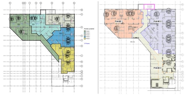
With a constant air volume, hard balanced air system with no terminal units for zone air flow control, how would we renovate one section of the ICU but yet maintain full operation of the non-renovated sections? The only way we could do this was to phase the construction. As stated, the phased construction was originally going to be completed in (5) phases (see figure 1) but due to the complexity and non-variability of the HVAC system, it was decided to complete the construction in (3) phases (refer to figure 2). Still challenging but doable.
Figure 1 Figure 2

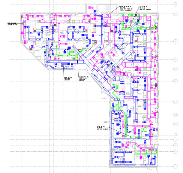
HVAC Layout figure 3
Phasing Options
Since the HVAC was the most complex system for phasing, I would like to share how we completed this task. The following is a brief summary of phase specific HVAC issues that were addressed during the design.
Phase 1:
- 5 of the 9 existing hot water reheat coils required relocation due to new wall conflicts.
- Large downstream 36x14 supply duct branch main affected phase 1 work. Rework of this branch was required for new zone supplies.
- Downstream 22x12 supply duct branch main affected phase 1 work. Rework of this branch was required for new zone supplies.
- Return Duct in phase 1 had multiple Boom conflicts therefore, Phase 1 return duct required rework. In addition, rework was required to allow for 9 foot ceilings.
Phase 2:
- 5 of the 10 existing hot water reheat coils required relocation due to new wall conflicts.
- Potential conflicts with patient Booms and return duct (potential because exact location of duct was approximate vs. measured): Return duct required modification. However, this same return duct serves the Phase 1 return duct work completed previously.
- Modification to branch ducts serving return duct grilles in Phase 2 work will impact return air flow rates in phase 1 completed previously.
- Balancing concerns likely between Phase 1 that will be negated when working on Phase 2.
Phase 3:
- 5 of the 10 existing hot water reheat coils required relocation due to new wall conflicts.
- It was anticipated that Patient Rooms 1 & 2 in Phase 3 would not be in use during Phase 2 work as both supply and return ducts for these two spaces required modification during Phase 2.
Required proper coordination for access to Phase 1 and Phase 2 spaces while phase 3 work was being completed. Refer to figure 2.
Proposed HVAC Phase Sequencing
Air flow between phases at best was designed such that the current phase work performed would be at a negative pressure to phases still in use.
The existing ICU was to remain operational with no AHU shut downs. Duct sealing would be compromised where the new duct connects to the existing to remaining duct as the mastic would need time to cure.
ICU patient rooms in general are kept slightly positive but is not a requirement as they have a No Requirement (NR) pressurization label per 2014 FGI. The Aii rooms do have FGI pressurization requirements and are required to be negative with respect to adjacent spaces. Any HVAC duct modification that communicates with the connected HVAC distribution duct systems either being removed from, or added to, was required to be scheduled during times of non-occupancy in the Aii Room(s) so that required pressurization relationships could be re-established in the Aii Rooms as needed.
- Phase 1: Temporary volume dampers were installed at supply duct opening created at the delineation points between new and existing to remain work. Portable HEPA Return units were provided and connected to return duct main at Phase 1 boundary such that all air returned from Phase 1 area is filtered prior to returning to the existing AHU. New temporary volume dampers installed on existing supply duct openings were modulated as required to create a condition where air leaving the Phase 1 boundary exceeds air being supplied to the Phase 1 boundary. Once new duct work was installed it was connected to existing duct work. Supply, return, and toilet exhaust air systems were tested and balanced.
- Phase 2: Supply side strategy was the same as in Phase 1. Return air duct main rework as noted above was required and impacted return air flow from Phase 1. However, reduction in return air flow from Phase 1 spaces resulted in the Phase 1 area being positive with respect to the Phase 2 area when this task was implemented. It was assumed that filtered return from completed Phase 1 area to Phase 2 are was required to minimize an over pressurization of Phase 1 area during this task. Installed new supply, return and exhaust duct work and connected to existing mains. Provided full Test and Balance of Phase 2 and rebalanced return of Phase 1.
- Phase 3: Was further evaluated after we had a better understanding of how access with completed Phase 1 & 2 areas was addressed in the Phase 3 scope of work. Supply side strategy was the same as in Phase 1 & 2. Once all Phase 3 HVAC systems were installed, final Test and Balance of Phase 1, 2 & 3 were performed.
MED Gases
- Phase 1: The following was proposed for the Med Gas portion of work:
- Provide portable Med Gas for Aii isolation Room located in Phase 2 scope of work.
- Valve off Phase 1 Med Gas Isolation Valves (Phase 1 Valve Isolation Station) serving Phase 1 and Aii isolation Room located in Phase 2 scope of work.
- Demo Med Gas piping from existing Phase 1 Valve Isolation Station serving Phase 1 spaces and Aii isolation Room located in Phase 2 scope of work.
- Install new Med Gas distribution piping and outlets to new Patient Rooms back to existing Phase 1 Valve Isolation Station and validate systems. Aii isolation Room located in Phase 2 scope of work to be served by new Phase 2 Valve Isolation Station.
- Phase 2: The following was proposed for the Med Gas portion of work:
- Construct new walls where new Valve Isolation Station cabinets are to be installed and install new Phase 1 and Phase 2 Valve Isolation Valve Cabinets
- Provide portable Med Gas for all Phase 1 Patient Rooms
- Valve off all Med Gas ICU branch main piping at second floor tie-ins
- Rework Phase 1 Med Gas piping from existing Valve Isolation Station cabinet to new Phase 1 Med Gas Valve Isolation Valve Station cabinet. Tie in new Phase 1 and Phase 2 Valve Isolation Valve Station cabinets to existing ICU-4 branch mains and associated alarm station pressure piping
- Validate Phase 1 Med Gas systems with new Phase 1 Valve Isolation Station
- Demo Phase 2 Med Gas piping
- Install new Phase 2 Med Gas distribution piping and validate.
- Phase 3: The following was proposed for the Med Gas portion of work:
- Provide new Med Gas piping to patient rooms from end of run Phase 2 Med Gas piping (not connected).
- Provide portable Med Gas for all Phase 2 Patient Rooms.
- Connect Phase 3 Med Gas piping to end of run Phase 2 Med gas piping and validate.
Electrical
Nurse Call (NC)
- Phase 1: The following was proposed for the Nurse Call System.
- The existing NC master station was currently in the proposed Phase 2 area. This would remain operational during Phase 1 construction to support the unconstructed areas.
- A new NC master station was provided for Phase 1 construction and remained operational during Phase 2 and 3 construction.
- Phase 2: The following was proposed for the Nurse Call System.
- NC system was temporarily disengaged until Phase 2 work completed.
- Re-engaged upon completion of construction.
- Phase 1 NC system remained operational.
- Phase 3: The following was proposed for the Nurse Call System.
- Phase 1 and 2 NC operational. Phase 2 NC would support the two patient beds in Phase 3 once completed.
- Phase 1 and 2 NC system synced.
Fire Alarm/Paging
Fire alarm and paging system remained operational throughout all phases. During phases, devices temporarily held in place and then reinstalled.
Power/Lighting
The existing normal, critical and life safety panels were reused as each phase was completed. Thankfully, the panels were within an existing dedicated electrical room. Each patient care area had both normal and critical power circuits installed on the perimeter but also on each Boom device. Life safety circuits were utilized for egress lighting as well as essential equipment as required by code.
As Phase 1 was being constructed, circuits were maintained in Phase 2 and 3 and vice versa as Phase 2 and 3 were constructed.
All lighting was composed of latest LED technology with dimming capability throughout. Lighting was designed to meet current energy code requirements.
Conclusion
Utilizing Revit for this project was a smart move. Working in cohesion with the architect allowed us to set the model up properly at the beginning. From that point on, the project went fairly smooth. It was a tremendous tool when it came to coordination of trades. This project was fun but yet very challenging. We had a great team of engineers and architects who worked in precision. I very much look forward to another opportunity such as this. Not only to manage but also to get my feet wet (again).
About the Author
Scott King is the VP & National Director of Electrical Safety Services. Scott has been with Hallam-ICS for over 30 years. Scott and his team have been conducting power system studies for over 15 years.
Read My Hallam Story
About Hallam-ICS
Hallam-ICS is an engineering and automation company that designs MEP systems for facilities and plants, engineers control and automation solutions, and ensures safety and regulatory compliance through arc flash studies, commissioning, and validation. Our offices are located in Massachusetts, Connecticut, New York, Vermont and North Carolina and our projects take us world-wide.
You May Also Like
These Related Stories

The Move to Revit

My Internship Taught Me the Importance of Company Values and Volunteering


Comments (1)