
by Jon McClain on Apr 22, 2021 10:30:00 AM

Recently, I had the opportunity to upgrade a customer’s control system from a network of four older Modicon Quantum PLCs (140 CPU 434 12) to later model Modicon Quantum PLCs (140 CPU 658 60).
Each of the PLCs must share data associated with local devices and software tasks across the network in order to function properly. With these requirements, we had to design a control network for the PLCs to communicate large amounts of data. In this example, we will outline how to initiate communication over Ethernet between two Modicon PLCs using the IO scanning function within the Schneider Electric Unity Pro XL software platform.
Step 1 – Set up and configure a Network Connection
To setup a network connection:
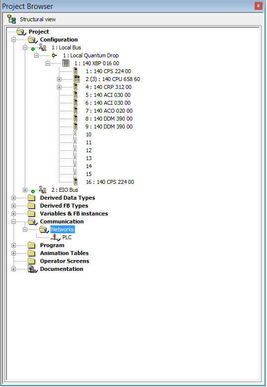
- Open the Project Browser in Unity Pro XL, and expand the Communication Folder.
- Right-click the Networks Folder and select New Network from the menu.
- Select Ethernet from the drop-down list, and name your network. I decided to name mine PLC. Note that the PLC network now shows up in the Networks directory.
 The new Network must now be configured. Double-click on the new network to open the configuration.
Select TCP/IP 10/100 Extended connection as the model family, as this model must be used with the given PLCs. On the IP Configuration tab, click Configured to setup the static IP address, subnet mask, and default gateway for the PLC. Be sure to select Ethernet II as the configuration type. Notice that the information at the top updates as the fields are populated. Under Model Utilities, make sure that IO Scanning is set to YES, while the other options are set to NO.
Inter-PLC communication can also be achieved using Global Data. This option is easy to implement and offers an efficient
solution by providing a common list of variables that are available to all PLCs on the network, but there is a limit to the amount of available data. Since we want the ability to transmit and receive larger amounts of data, IO Scanning is our best option.

Step 2 – Link Network Object to Physical Port
Once the network object is configured, it must be linked to the physical port in the hardware layout. Open Local Bus in the Project Browser and select the bottom picture of the RJ-45 jack on the CPU module to open the ETHERNET_CPU port.
When the ETHERNET_CPU menu appears, choose the network you created from the dropdown. If the network name does not appear, make sure that the model family is set to TCP/IP 10/100 Extended Connection in the network configuration screen.

Once the link is made, the icon of the network will change to an icon of a PLC rack:
Now that the network connection is made for a PLC, the network architecture should be considered. The IO scanning option uses a simplified version of the Modbus TCP/IP protocol. Modbus TCP is an Ethernet-based version of Modicon’s Modbus RTU serial protocol (RS-485), which is a widely-used open-source industrial communication platform. With the invention of Ethernet, Modbus RTU was adapted to Modbus TCP/IP, while still maintaining openness and flexibility. The Modbus Master (or client) cyclically executes records containing the addresses and write/write instructions for blocks of data. A quick internet search will return a massive amount of information on Modbus RTU/Modbus TCP, so for the sake of brevity, an explanation of the inner workings of the system will be omitted from this example of communication between the Modicon PLCs, using the IO Scanning function.
Step 3 – Setup PLC Registers
Once we have the data that we want to pass, we need to setup the registers in our PLCs that will be designated for communication. To see available memory, go to the PLC menu in Unity Pro XL, and select State RAM Viewer. Since IO Scanning uses 16-bit registers as its targets and destination for reading and writing, select the %MW space, and check all of the boxes for modules, variables, and language to see truly available space to store data received over the network. 
For PLC1, which is acting as the Master, there seems to be free space around the %MW500 address, so that will work for the exercise. Now, we must choose which data we need to read or write from the Slave, PLC2. The first exercise is trying to read a memory space in PLC2.
By using the State Ram Viewer on PLC2, find an open address in the %MW space. In our case, PLC2 has a free space at %MW800. Open the Network object on PLC1, and select the IO Scanning tab.
To create an IO Scanning record, enter the IP address of the PLC to read from. The IP address for PLC2 is 192.168.10.93. The Unit ID is used to access different MBTCP slaves within the same server (with the same IP address). Again, more information is widely available on this topic, but for this exercise, the Unit ID must be 1. The Slave syntax is a little more complex without any prior Modbus knowledge. Since we want to use addressing format %MWxxxx instead of the raw address format (4xxxx), and since the addressing begins with %MW1 instead of %MW0 in the Modicon PLCs, select IEC1 from the dropdown. The health timeout and repetitive rate are adjustable, so we will leave them at the defaults for our exercise. Since we want to read one register at %MW800 on PLC2 and save it to one register at %MW500 on the master side, the IO Scanning record is setup as shown below:
 Since we are not making any writes at this time, the WR length is 0. Open PLC2, and create a new Animation Table in the hardware tree. Add %MW800 as a variable to read (even though it is an address, not a variable name). Click Modification, and change the value of the address.

On PLC1, build the project and transfer to the PLC. After the transfer is complete, create an animation table with %MW500 as the variable name. The address should show the value entered on PLC2.
 An Example with Multiple Data Types

For a more advanced example, I created a data structure composed of different data types on Both PLCs:

And for PLC2,

Where we want to read TestBOOL, TestINT, and TestREAL, and write to TestDINT and TestBYTE. The IO Scanning record now becomes:
The RD length is 4 by adding the registers of the BOOL (occupies one register, even though it only uses one bit), INT (one register), and REAL (two registers). The WR length is DINT (two registers) plus BYTE (occupies one register, even though it only uses 8 bits). By adding the structures into their respective animation tables in Schneider Electric Unity Pro XL:
The values of TestBOOL, TestINT, and TestREAL modified on PLC2 (right) are read by PLC1, and the values of TestDINT and TestBYTE modified on PLC1 are written to PLC2.
At Hallam-ICS, our team of skilled Process Control Engineers fosters an environment of collaboration, curiosity, and tenacity. From Batch Process to Machine Control, we succeed by investigating problems thoroughly, designing and implementing efficient solutions, and communicating effectively with our customers for comfortable transition to ownership.

About the Author
Jon has left Hallam-ICS to pursue other endeavors, but his contributions to the company continue to be valued.
About Hallam-ICS
Hallam-ICS is an engineering and automation company that designs MEP systems for facilities and plants, engineers control and automation solutions, and ensures safety and regulatory compliance through arc flash studies, commissioning, and validation. Our offices are located in Massachusetts, Connecticut, New York, Vermont and North Carolina and our projects take us world-wide.


How to Create Email Notifications Using OSIsoft PI Data Server, Rockwell Data Historian, and Microsoft SQL Server

Equipment Energy Usage – My Favorite MI Project in 2017

Comments (5)