
by Jeff Silcox on Sep 19, 2019 10:01:00 AM

In Part 1 of our series, we talked about cryo electron microscopy (cryo-EM) and scanning transmission electron microscopy (S-TEM), their sensitivity and the deleterious effects that the ambient environment can have on microscope performance. We discussed the importance of site selection and the recommendation to retain a vibration consultant to assist in evaluating your proposed installation location(s). Once a site has been chosen, and funding is approved, it’s time to design the microscope lab.
Architectural Features Have Lasting Impacts
As engineers, we are tempted to think that the environmental performance of a space has everything to do with our MEP building systems. However, having worked for many years in the Advanced Technology Industries, we understand that the architectural features of a facility also contribute to its successful environmental performance. This is true for a cryo-EM laboratory as well. Entering the design phase of the lab, the decisions and choices that we make, relative to the laboratory layout, materials and details of construction, will have lasting impacts on microscope performance.
While vibration, noise and electro-magnetic interference (EMI), from both alternating (AC) and direct (DC) current sources are enemies of microscope performance, contamination and excess humidity also diminish performance. Assuming that a careful site selection has eliminated or mitigated some of these factors, we are left to address the remainder through good laboratory design practices.
The microscope manufacturer will furnish specifications for cleanliness, EMI, acoustics, vibration, temperature range, temperature drift, air velocity and relative humidity that must be provided within the laboratory. Typical requirements are for an ISO 8 (Class 100,000) cleanroom environment, quiet, stable temperature with low relative humidity, EMI and vibration.
4 Questions to Ask
Some of these factors can be addressed directly through the facility layout and careful consideration of the following questions:
- How will the researchers interface with the microscope, locally or remotely?
- Where will samples be prepared?
- How will microscope service be performed?
- Where will the mechanical/electrical equipment serving the lab be located?
While each end user will have their own unique set of needs, as general design guidelines, we like arrangements where lab personnel spend as little time as possible in the microscope room, where segregation from adjoining building spaces is provided, where mechanical/electrical rooms are separated from the microscope room and where samples are prepared in a dedicated space away from the microscope room. Following these guidelines often results in a laboratory footprint, containing a microscope room, anteroom/control room, sample prep lab, mechanical/electrical room and possibly an equipment maintenance room.
We find that combining the anteroom/control saves space in the lab and works well operationally. It also physically segregates the microscope room from the remainder of the building. If a viewing window is incorporated between the anteroom/control room and the microscope room visitors/observers will never need to enter the microscope room, and researchers only occasionally. This reduces the potential for contamination, reduces noise and improves temperature/humidity stability in the microscope room. Unless shielding is to be provided, locating electrical transformers at least ten (10) meters away from the microscope will be necessary to avoid AC EMI. Following this methodology naturally introduces distance/space between the mechanical/electrical room and the microscope room, helping with the acoustic requirements as well. For biology work, the sample prep lab will likely be contiguous with the rest of the facility, while physical sciences may be able to do the prep work remotely.
In the microscope room, be sure to consider the space requirements, including electrical clearances, for the microscope accessories when laying out the room as they eat up a surprising amount of it. Also consider that your research group might have their eyes on other accessories or upgrades that will require even more space in the future. Ceiling height is important, not only for microscope maintenance, but for sound attenuation too. Allowing a few extra feet of floor space and a little more ceiling height, now, could save some big headaches later.
Focus on the Details
Once the microscope laboratory layout has been agreed upon, it’s all about the details and how we use them to assure, and improve, microscope performance.

Materials
- In ISO 8 environments, we look for surfaces that are easy to clean, such as epoxy flooring and epoxy painted walls.
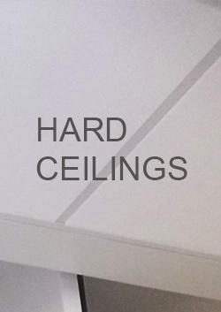
- We also like hard ceilings (i.e. gypsum wallboard, epoxy painted). Cleanroom ceilings (coated gyp-board tiles, secured to a sealed ceiling grid) can also be used, although typically at a higher cost. An advantage of the gypsum board ceiling is that it can be applied in a double layer, with rock wool or fiberglass insulation above, providing a real sound attenuation benefit. If the mechanical equipment has been thoughtfully separated from the microscope room, there will be no need for access panels in the ceiling above the microscope.
Sound
For sound attenuation, there are many details to consider.
- Concrete block (CMU) covered with wood furring and gyp-board is one of our favorites, but can be more expensive.
- Other options involving wood studs, rock wool insulation, air gaps and multiple layers of gyp-board can achieve comparable results.
Open wall penetrations for plumbing, fire protection, electrical and computer cables are all pathways for sound transmission. The details for sealing them should be well thought out. Thinking of the microscope room as something akin to a recording studio is helpful at this point. Density of assemblies, insulation and air gaps all have a role to play. Doors should be specified with an STC 52 rating, and that window between the control room and microscope room, it should have one too.
 Speaking of doors, unlike a swinging steel door, a wooden door will not interrupt the magnetic field around the microscope (DC EMI). Wooden wall studs and furring do not have the ability to conduct electricity, a potential source of AC EMI, so choose wood over steel for these elements, where you can.
Humidity
Environmental stability in the microscope lab is improved with the addition of thermal insulation. In so doing, you will also pick up a nice bonus sound attenuation benefit. While the space humidity requirements may not be that stringent for a given microscope (up to 80% rH), the specifications will typically indicate that better performance will be achieved in a dryer space. We agree. With this in mind, you may want to think about vapor barrier requirements, especially if the microscope lab is located in the basement level of the building.
Vibration
Finally, there is vibration to consider. If the pre-design site survey, by your microscope vendor, indicated ambient sources of vibration (e.g. trains, subways, highways), then you may need an inertia base under the microscope. If so, you’ll need to hire a specialist for this one. Otherwise, keep in mind that when it comes to vibration in a building, just like in a cast iron machine tool base, “mass and stiffness are your friends”. If you are going to be placing a new slab on grade for your microscope room, consider adding a few extra inches of concrete to it, you won’t be sorry later.
Summary
We have talked about many details in this article and it is also true that there are many paths to a successful design. Perhaps what’s most important to remember is that for optimal microscope performance, the details matter, especially as they pertain to understanding and mitigating the sources of disturbance to your microscope’s performance.
In our next post we will discuss the MEP aspects of cryo-EM laboratory design, how these systems provide both a suitable environment for the laboratory, while at the same time contributing deleterious side effects and how to mitigate them.


About the Author
Jeff has retired from Hallam-ICS, but his contributions to the company continue to be valued.
Read My Hallam Story
About Hallam-ICS
Hallam-ICS is an engineering and automation company that designs MEP systems for facilities and plants, engineers control and automation solutions, and ensures safety and regulatory compliance through arc flash studies, commissioning, and validation. Our offices are located in Massachusetts, Connecticut, New York, Vermont and North Carolina and our projects take us world-wide.


How PlantPAx Certification Ensures Your Project Success

The Adventures of Becoming a Phishhead- 80 Shows and Counting

No Comments Yet
Let us know what you think