
by John-Michael Taylor on Aug 10, 2023 10:30:00 AM
I recently worked on a wastewater upgrade project at a pharmaceutical plant which involved deploying a Hach B7000i Total Organic Carbon (TOC) Analyzer. The team was composed of engineers and technicians from the client, multiple wastewater experts, and from Hallam ICS.This blog describes some of the important lessons learned about periodic sampling (versus continuous) measurement instruments and some of the challenges encountered with the digital interface of the Hach B7000i.
I initially gave very little thought to the TOC analyzer aspect of the project. I imagined that I would have access to a TOC reading with which to make decisions about where to direct the wastewater -- either into the Moving Bed Biological Reactor, MBBR, or directly to the effluent monitoring tank in the event that Biochemical Oxygen Demand (BOD) was determined to be within acceptable limits for disposal.
The Hach 7000i TOC Analyzer has 4 sampling ports. In the wastewater facility described here, water was sampled at the outlet of each of 2 Equalization tanks, EQ1 and EQ2, at the outlet of the MBBR, and at the outlet of the effluent monitoring tank which could either be sent to a lift station or back into EQ1 for further processing.
The B7000i instrument does not continuously measure TOC, but rather it periodically performs measurements on samples of wastewater from a sample bottle attached to one of its 4 sampling ports. The flow through the sample bottle is controlled by a regulating valve on the bottom of the bottle. The wastewater flows through and fills the sample bottle, and the effluent is pumped back into the wastewater stream. The B7000i uses a series of peristaltic pumps to pump material from the sample bottles into the instrument to make a TOC measurement. Following the measurement, the analyzer back flushes the sample line with acid/ base (the acid/ base is needed for the TOC measurement, I don’t really understand all the chemistry) and pumps this mixture back into the sample bottle. As a result, the sample bottles must be adequately flushed and refilled with “fresh” wastewater to be measured prior to each measurement. Furthermore, the sample bottles are only flushed when there is flow in the section of piping where the sampling point exists. That means that the pumps in the facility that feed the lines being sampled must be running for a certain amount of time to adequately refresh the sample bottle.
The B7000i has a basic user interface screen to setup and configure sampling at each of the 4 sampling ports. The firmware does not have the ability to configure different measurement intervals for each sample point. All sample points are measured at the same time interval, with the sample point measurement order according to the configuration parameters. Fortunately, the instrument has a remote command / control capability via a series of Modbus registers within the controller that can be leveraged by a PLC to extend the basic functionality of the firmware. With the requirement to have certain pumps run for a certain length of time and the requirement to have different sampling intervals for the different sample locations, I needed to control the B7000i more tightly than was possible from the basic configuration afforded by the instrument’s firmware.

It became very clear, very quickly, that the local technical support team was not very familiar with the remote command / control interface of the B7000i. It was not the team’s fault; it was just that the interface is a relatively new feature of the instrument and as such was not very well documented yet. I had to reverse-engineer the remote MODBUS register interface by watching dozens of TOC measurement cycles to understand the instrument behavior. So much for simply receiving periodic TOC measurements…
Implementation
The following is a description of the PLC logic that was implemented to extend the functionality of the B7000i native firmware. The software was designed to afford the system the ability to have configurable and independent sample measurement intervals for the sample points, and to ensure that the sample lines were adequately flushed and filled prior to a measurement being taken.
The B7000i is controlled via a finite state machine (FSM) implemented in the PLC. Figure 1 is a graphical representation of the FSM design. The figure shows the detailed interaction between the PLC and the B7000i via the MODBUS registers. This state machine moves the analyzer through its paces to make a measurement of one of the four sampling points at a time. The PLC is in constant bidirectional communication with the analyzer via the Modbus registers in the analyzer. The PLC logic moves through the various states of the FSM by reading status feedback from and writing recipe information and commands to the analyzer. The “recipes” contain the sample point to be measured and the measurement range that the analyzer is to use for that sample point.
The state machine is B7000i centric and mirrors the states that can be read from the MODBUS interface, and that are seen on the instrument’s small display screen. The following states are defined:
- ERROR: The PLC is continuously reading back the same Modbus registers that it is writing. The Error state is entered if at any time the PLC determines that the Modbus writes were not successful. Additionally, there is an alarm Modbus register that the PLC continuously reads and will enter the ERROR state if the B7000i is in a fault, warning, or notification state.
- STOPPED: wait for a sample point to be queued up for measurement. If the measurement queue is populated, take the first recipe and command the B7000i to start the measurement.
- Startup: the B7000i goes through a startup process each time that it comes out of its “Stopped” state. In this state, the PLC is waiting for feedback that the instrument has completed “Startup”.
- Quick Startup: the B7000i goes through a quick startup process prior to each measurement. In this state, the PLC is waiting for feedback that the instrument has completed “Quick Startup”.
- Total Inorganic Carbon (TIC)/ Base Oxidation: the instrument pumps material from the sample bottle and performs TIC/ base oxidation process.
- SYNC HI: the instrument sends a synchronization signal to the PLC, signaling that the PLC can request that the instrument go into “remote standby” mode when the current measurement has completed.
- TOC: the instrument performs the TOC measurement at the range requested by the PLC recipe
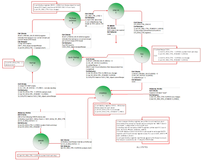
Figure 1: PLC Finite State Machine that controls the HACH TOC Analyzer sampling process.
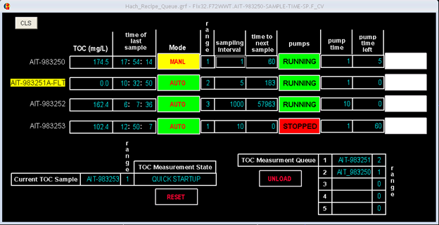
Figure 2: TOC Analyzer control interface
Figure 2 shows the user interface that is used to drive the TOC measurements. The top of the display shows the last TOC measurement for each sample point and the time of day associated with that measurement. The current state of the PLC/TOC analyzer interaction is shown on the bottom left-hand side (it is “QUICK STARTUP” in this snapshot). A manual “RESET” button allows the operator to force the PLC to go to the “idle” state in the event that the PLC and analyzer lose communication synchronization.
The PLC logic implements a recipe queue (FIFO) that stores an ordered list of upcoming measurements. Sample recipes are pulled from the top of the list one at a time when leaving either of the 2 startup states and written to the B7000i. The B7000i must receive the recipe for its next measurement after TIC/ base oxidation has started but BEFORE its SYNCH signal is set. This was discovered by running the instrument through many measurements and monitoring the MODBUS registers in order to understand the behavior.
The scheduled queue is displayed in the bottom right-hand corner of Figure 2. A manual “UNLOAD” button allows the operator to manually pull scheduled measurements from the list if required, allowing a scheduled measurement to be skipped. The recipes are unloaded one at a time with each successive press of the “UNLOAD” button.
Each sample point can be put into Auto or Manual mode. In Manual mode, the sample point can be added to the sampling queue by pressing the “SAMPLE” button seen in the popup in Figure 3.
In Auto mode, samples are added to the queue when the sampling interval for that sample point expires, the pump run time requirements have been met, and all permissives for that sample point have been met.
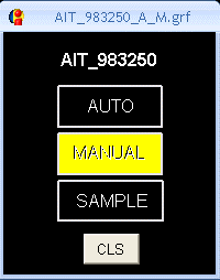
Figure 3: TOC sample point AUTO/ MANUAL selection interface
The PLC logic associates each sample point with the A/B pump pair that is required to run to flush and refill the sample bottle for that point. There is an operator configurable “pump time” parameter on the operator interface. This is the amount of time that one or both pumps associated with a sample bottle must run before that sample point will be added to the queue. The pumps do not have to run continuously for this amount of time, just cumulatively between successive measurements. The operator interface also displays the amount of required pump running time remaining.
The time remaining until the next measurement is scheduled is displayed for each sample point. If this measurement interval timer elapses before the pump timer, the sample point will not be scheduled and added to the measurement list until the pump timer expires.
In closing
The deployment of the Hach B7000i Total Organic Carbon (TOC) Analyzer for the wastewater upgrade project presented both valuable lessons and challenges. The project highlighted the importance of understanding the periodic sampling nature of the instrument and the need for precise control over its operation.
Despite the initial lack of familiarity with the interface and the need to reverse-engineer its behavior, by leveraging the remote command/control capabilities and implementing a PLC-based finite state machine, I was able to successfully integrate the instrument into the existing control system. By overcoming these obstacles, I was able to optimize the wastewater treatment process and allow the client to make informed decisions based on accurate TOC measurements.
About the Author
John-Michael joined the Mansfield, MA office as a Senior Controls Engineer in 2020, bringing with him over 20 yrs of experience in automation and controls in various industries. He has left Hallam-ICS to pursue other endeavors, but his contributions to the company continue to be valued.
Read My Hallam Story
About Hallam-ICS
Hallam-ICS is an engineering and automation company that designs MEP systems for facilities and plants, engineers control and automation solutions, and ensures safety and regulatory compliance through arc flash studies, commissioning, and validation. Our offices are located in Massachusetts, Connecticut, New York, Vermont, North Carolina Texas and Florida and our projects take us world-wide.


GLP Temperature and Humidity Data Migration During BAS Upgrades: Why It Matters

Lessons Learned in Project Management: How to Improve Performance and Avoid Repeat Mistakes

No Comments Yet
Let us know what you think