
by Thomas Toppin on Apr 21, 2022 10:30:00 AM
I recently had the opportunity to work on a project for a client of ours utilizing Schneider’s Unity Pro software and M340 PAC’s. The project was a typical groundwater remediation site which included multiple treatment facilities and remote wells, all of which communicated with each other over a new cellular network.Interconnectivity between all the sites was necessary not only to be able to control the remote sites from the local treatment facilities HMI, but also to ensure the treatment facility was capable and ready to receive the untreated water.
I have done many remediation projects in the past, however this was the first time I had ever used Modicon as the PLC platform and cellular as the communications media. Both were pretty large learning curves. Overall the project went pretty smoothly considering the lack of experience in both areas. A few months after startup had been completed I was notified by the client that they were experiencing intermittent communications failures between a few of the sites. I immediately thought the failures were probably related to the cellular network and began looking down that road. With the help of the cellular modem’s tech support team I was able to rule out that the network was the culprit. I then set up some data logging and automatic emails to try and establish when the failures occurred, but there was no rhyme or reason as to when they happened. Anyone that programs knows how tough intermittent communications failures can be to resolve and this one was no different.
I began to review the messaging logic (which I copied from an existing project) and realized that the way the messages were being executed didn’t make much sense. Specifically with remote communication networks I was always taught to cycle through the messages, executing one at a time. When that message completes successfully or fails then move onto the next. The existing logic executed all the messages at the same time (on the same scan) by calling a Function Block Diagram (FBD) routine that contained all the message instructions. The routine was called every minute since the data isn’t that critical and I was trying to limit the cellular data usage.
In the end I decided to re-write the messaging logic however this wasn’t as easy as I thought. The READ_VAR and WRITE_VAR instructions don’t provide status bits that tell you when the message completes with or without error. What they do provide is an array of data four integers long called the “Exchange management table” that can be used to gather the same data. 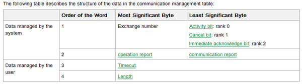
I created a Derived Function Block (DFB) that breaks out the data into a more user friendly format that could be used to cycle the messages like I intended. 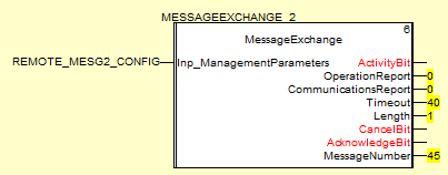
Each byte of the exchange management table had to be extracted and put into individual registers. This is an example of how the communications report was extracted.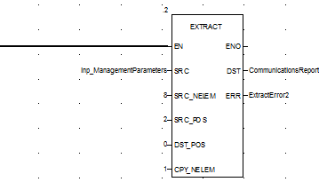
The information that I really needed was the activity bit and communications report. When the activity bit goes high I can verify that the message has been executed. The communications report will tell me how successful the message was and will generate an error code if something went wrong. If the communications report returns all zeros then the message was successful. Once the DFB was created I could use it over and over for each message that I had.

So now that I had the data necessary to cycle through each message I had to think of an easy way to utilize it. I decided to use a Sequential Function Chart (SFC) routine which cycles through a set of predefined steps, executing one at a time and waiting for each step to complete before moving onto the next. This would allow me to easily execute 1 message at a time rather than all of them at once. I created steps for each message which executed and then tested the message. If the message was successful it would move onto the next message. If it was not successful the logic would drive a communications failure bit that would interlock upstream equipment and notify operators via email and local alarms. The logic would then move on to the next message. The SFC made it easy since there are built in timers and action bits for each step that I could use to enable and delay each message.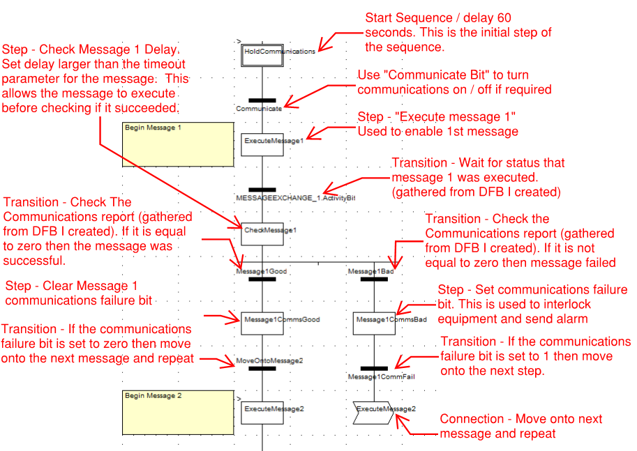
This logic can be copied over and over for the number of messages that are required. The last message will connect back to the initial step and the process will occur all over again. In this example there were 7 messages. The end of the SFC would look like this.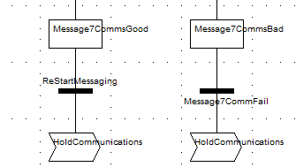
Since the initial step can have a delay there is no need to make the SFC routine conditional if you would only like to poll the devices intermittently and can simply be called all the time. The Ethernet messaging routine can also be unconditional since each message is only enabled based on the current step of the SFC routine. Each message instruction would be setup like this.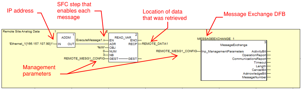
The end result was an easily configurable, scalable way of controlling the messages that can be re-used for almost any application.
About the Author
Tom Toppin is a Process Controls Engineer for Hallam-ICS. Tom started his career as an Electrician and has over 17 years’ experience designing, installing & troubleshooting electrical systems. Since becoming a Controls Engineer Tom has developed and commissioned a range of systems and his areas of expertise include continuous processing, batch processing, SCADA, water and wastewater.
Read My Hallam Story
About Hallam-ICS
Hallam-ICS is an engineering and automation company that designs MEP systems for facilities and plants, engineers control and automation solutions, and ensures safety and regulatory compliance through arc flash studies, commissioning, and validation. Our offices are located in Massachusetts, Connecticut, New York, Vermont and North Carolina and our projects take us world-wide.


3 Easy Steps to Share Data Between Modicon Quantum PLCs Using Schneider Electric Unity Pro XL

Rock Paper… You gotta be kidding me

Comments (1)