Analog Fieldwork and Design in the 21 Century
by William Neuburger on Apr 13, 2023 10:30:00 AM
Retrofit is a nontrivial part of our firm’s scope of practice. Our clients often need new systems installed in and around existing systems instead of standing up a nice new building. Sometimes this work is straightforward; for example, route a few small diameter pipes and one electrical conduit across a mechanical room. Other projects demand larger equipment and utilities in crowded spaces. At Hallam-ICS we relish the more difficult projects.
Sometimes for retrofit work we deploy laser scanning as a modern way to document the geometry of a various project. This process generates a point cloud which resolves to something akin to a three-dimensional photograph. The scanning contractor turns over a point cloud model and we use specialized software to navigate through it. We can make measurements of the existing elements, diameter, length, angle, etc. It is a powerful tool and feels very modern.
In 2021 on a west coast project, the owner engaged a specialty firm to make laser scans of about 10,000 square feet of their existing building. Their scanning took under one day and produced 1,845,245,677 “triangles, lines, and points.” That’s 1.8 billion objects. The result was a 132-gigabyte file, too large to reliably transfer over the internet. They shipped us an external hard drive. My colleague Leigh had to copy the file to his computer to use it.
Once we had the file on a computer and mastered the software, we were able to use the model as a valuable tool for us to plan the expansions to an existing helium recovery system. The owner was considering installing a triaxial liquid helium line to convey liquid helium to a new phase separator that would serve two semiconductor research tools. We did the process engineering on the original liquefier installation in 2019 and the project architect used a laser scan to guide the layout of the new equipment in the existing building.
We enjoy and appreciate the power of modern tools like laser scanning and modeling, some projects scales and sizes do not lend themselves to the cost and complexity of a scan. We are working on two projects in 2023 that include adding relatively large piping to existing, crowded places.
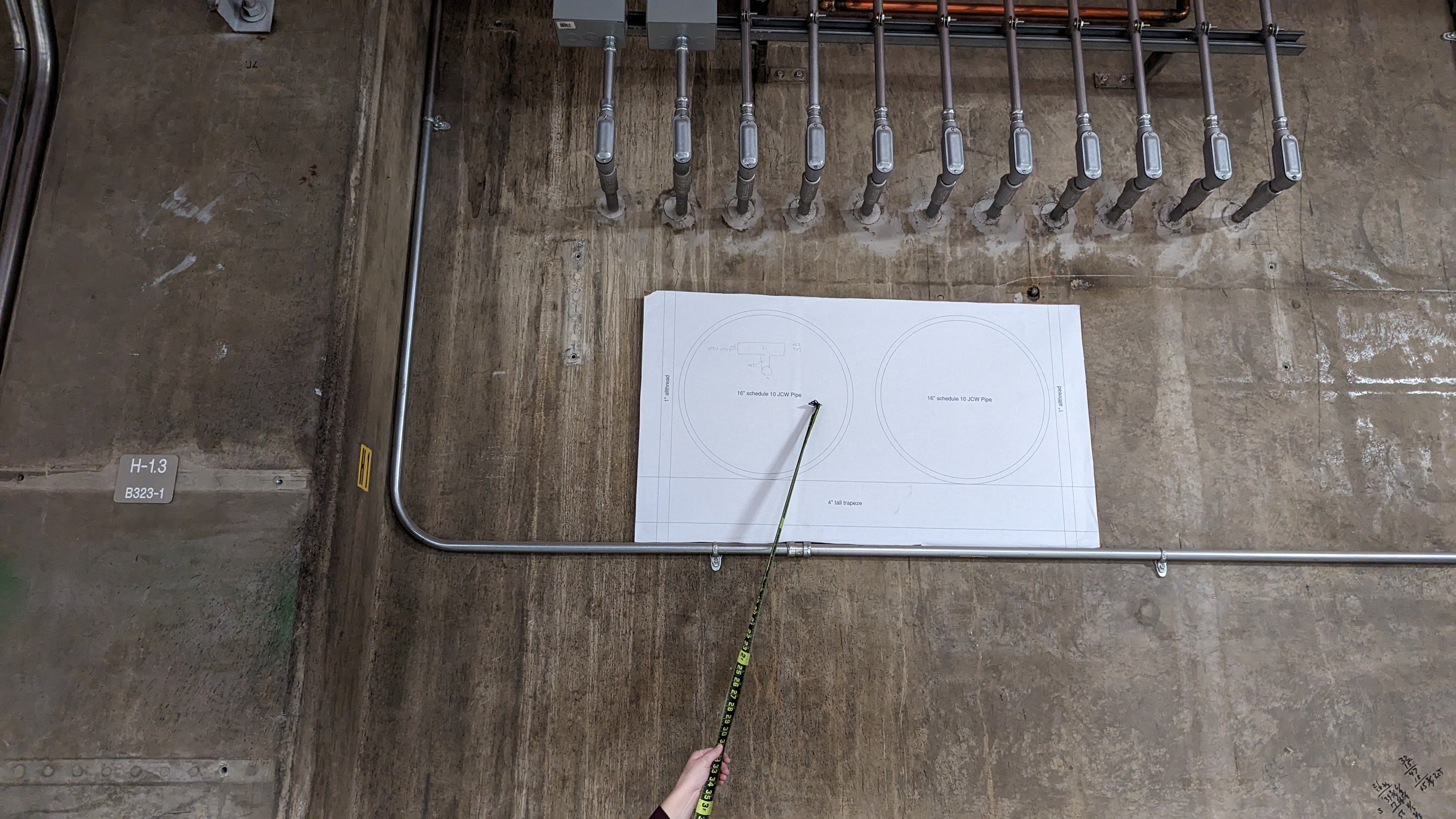 Observing the feasibility of passing two 16” process cooling water pipes through an existing wall.
One project involves adding new 16” process cooling water piping and 12” insulated chilled water piping in the ceiling of an existing semiconductor fabrication facility to reinforce existing process cooling systems. The subfab (industry slang for the level below the clean space) is about 550 feet by 300 feet, with literally thousands of conduits, cable trays, pipes, tubes, and stretches of ductwork. A laser scan of this space and the systems would take days to produce, and the file size would be unwieldy. Breaking the file up to zones to limit the file size would be nonoptimal for us, as our piping must extend to essentially every corner of the space.
I made 1:1 scale drawings of the different piping configurations and our colleague Jen printed them on our plotter. She used her craft skills to affix the prints to cardboard and cut them out neatly. My colleague Tori and I brought the cardboard exemplars with us and carried them around the subfab to see what was feasible and what was not for pipe routing.
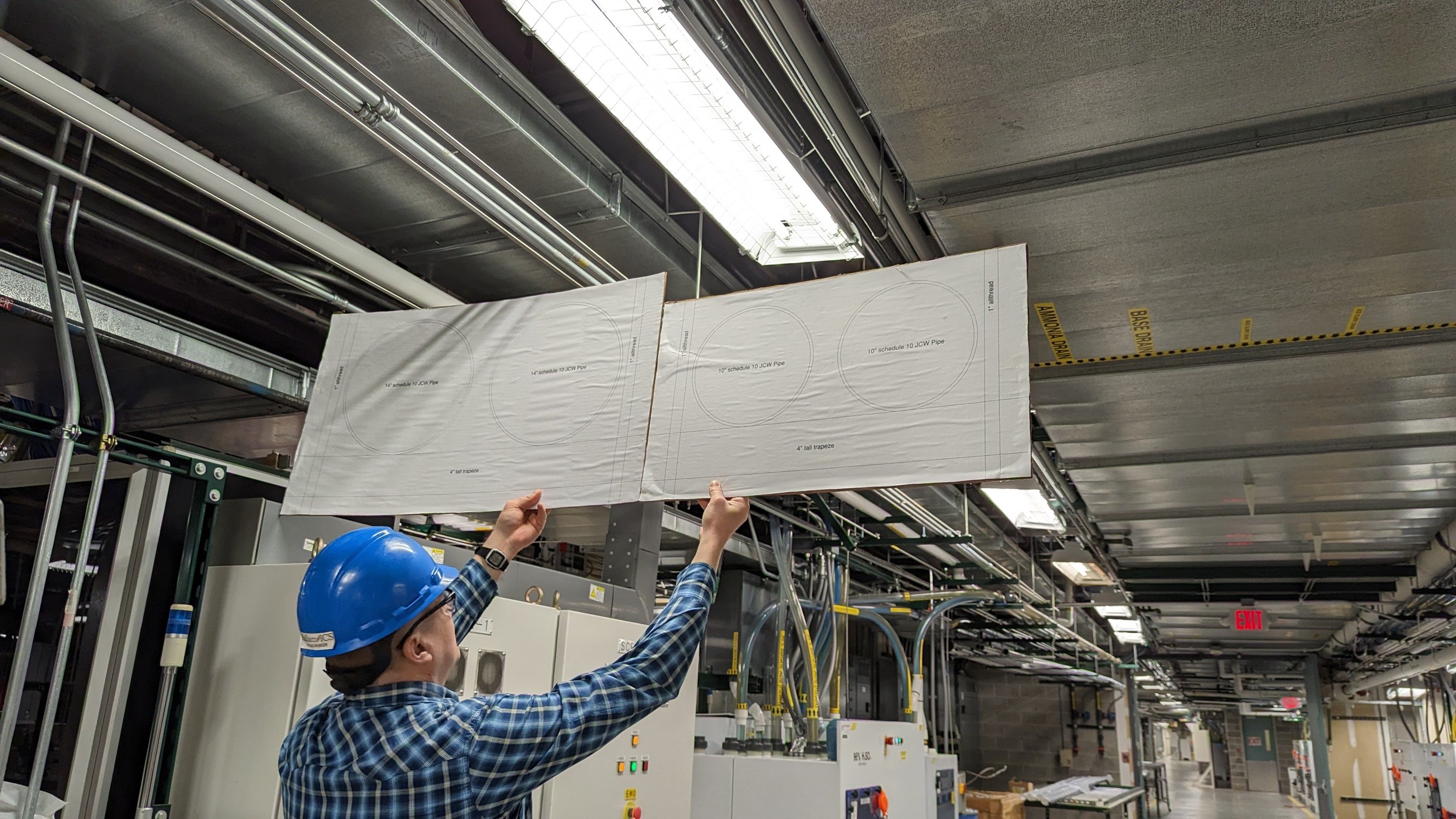
Planning a route for a parallel set of process cooling water pipes, 14" and 10".
Another project involves bringing new 130 psig, 12” steam pipe (nearly 24” in diameter when including the 5” thick insulation) about 1,000 feet from one end of an existing utility tunnel to an existing boiler room. The tunnel appears spacious when walking around and imagining the pipe route. Appearances and reality are often different, especially when it comes to welded carbon steel piping in existing locations. We created a set of 1:1 scale cardboard mockups of different pipe sizes (thanks again to Jen and her skills with a scissor) and brought them with us to the tunnel.
.jpg?width=2688&height=1512&name=3%20(1).jpg) Spotting the location of a 12” 130 psig steam pipe with insulation.
Spotting the location of a 12” 130 psig steam pipe with insulation.
After a few hours of walking around (and under, and behind) existing piping systems we found a route that appears to work. Though we performed our cardboard exercise for route planning, we may laser scan this tunnel and existing supports instead of spending 2-3 days measuring to the to the nearest millimeter.
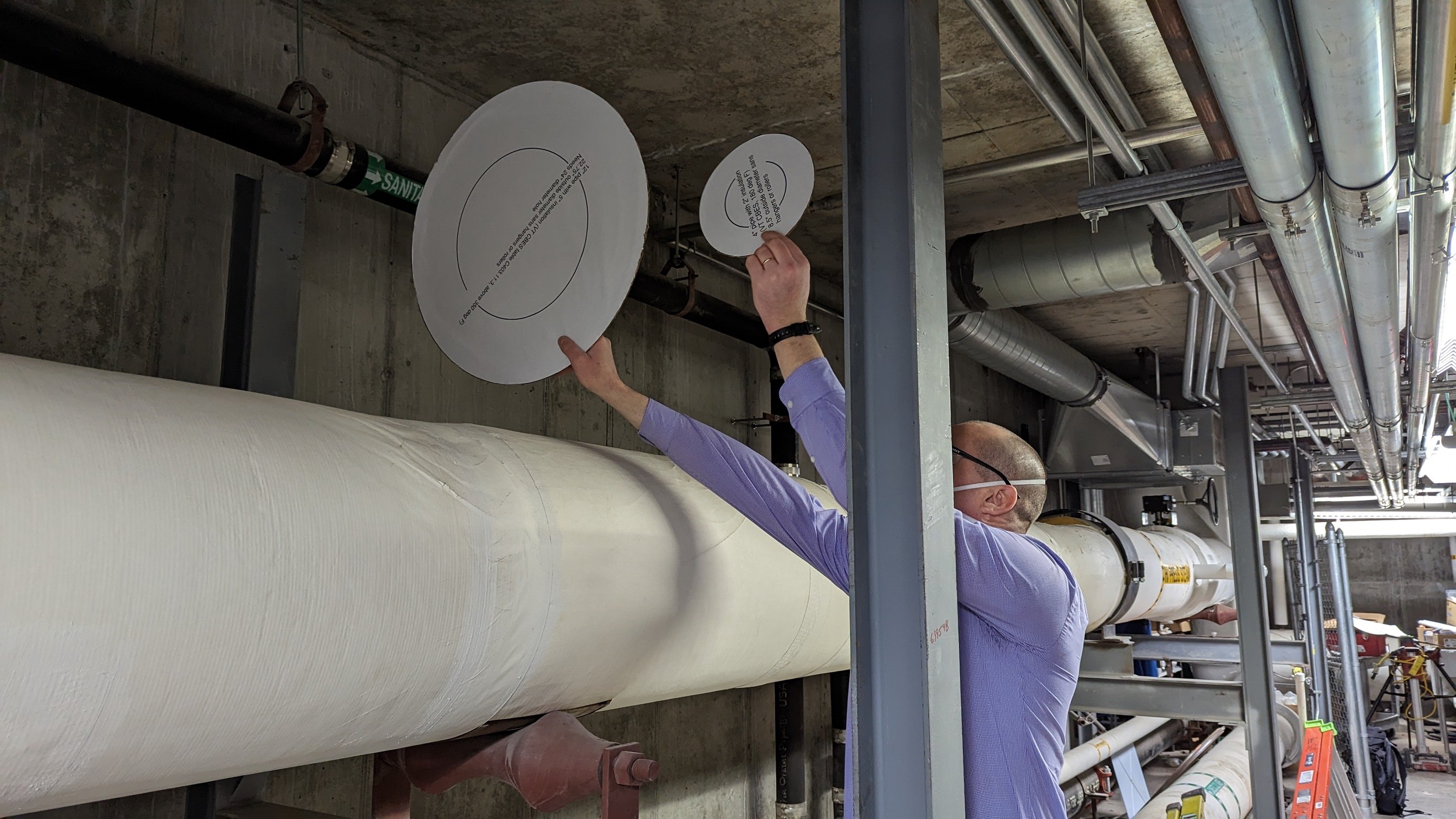
Considering the route of a 12” 130 psig steam pipe and 4” condensate pipe, both with insulation. We discovered this particular location is nonviable, there is an existing pitched drain line that crosses perpendicularly.
Part of why I enjoy my career at Hallam-ICS is the variety of projects, clients, and tools we use. There is fun in selecting the right tool for the job, the right colleagues for a team, and eventually the right systems to safely serve the client’s needs. Sometimes we use lasers, powerful software, multiple subcontractors, and colleagues. Sometimes two of us walk around in a hospital basement with big discs of cardboard.
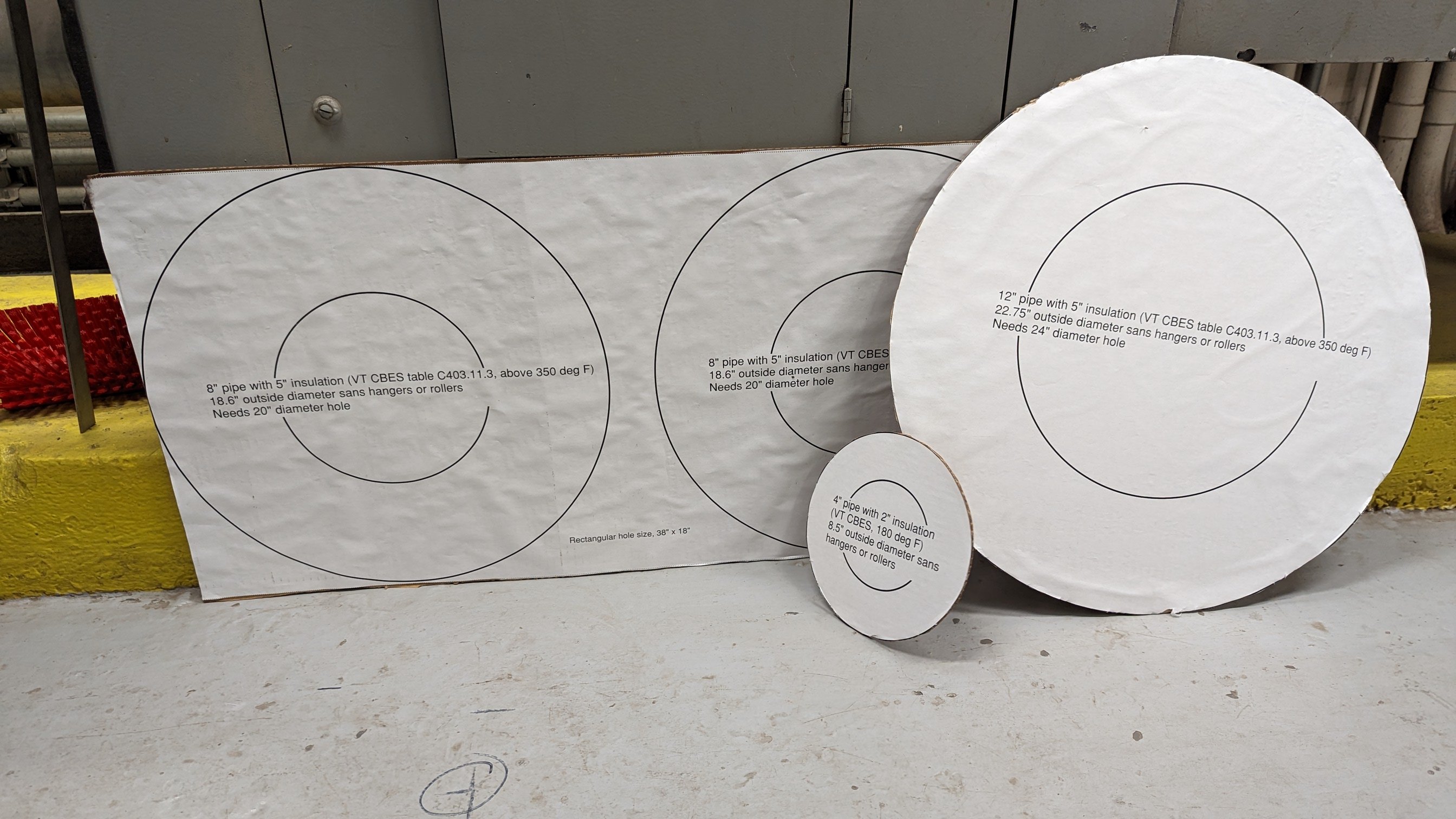
Tools of our trade, a 12” steam pipe, with pair of 8” steam pipes (equivalent for our conditions as a single 8”), and a 4” condensate line.
About the Author
Bill has been a mechanical engineer since 1995 and with Hallam-ICS since 2010. His career has brought him to the top of the Transamerica Pyramid Center, chemical plants, underground mines, paper mills, and semiconductor fabrication facilities. He has experience designing, specifying and installing mechanical and electrical systems in the built environment covering industrial, institutional and commercial facilities.
Read My Hallam Story
About Hallam-ICS
Hallam-ICS is an engineering and automation company that designs MEP systems for facilities and plants, engineers control and automation solutions, and ensures safety and regulatory compliance through arc flash studies, commissioning, and validation. Our offices are located in Massachusetts, Connecticut, New York, Vermont and North Carolina and our projects take us world-wide.
You May Also Like
These Related Stories

8 Steps to Create an Electrical Safety Program Part 4

Reducing Carbon Emissions by Electrification


No Comments Yet
Let us know what you think