Arc Flash Detection Relays: Stopping an Arc Flash at the Speed of Light
by Chris Font on Jan 18, 2022 10:30:00 AM

Background
It is well known that the energy released during an arc flash event is governed by three variables.
- The magnitude of the fault current
- The working distance
- The duration of the fault
The amount of energy released during an arc flash is directly proportional to the duration of the fault. The obvious goal would be to reduce the clearing time of the protective devices as much as possible, as a reduction of time by half reduces the overall energy released also by half. Dependent on the specific device responsible for clearing the fault, typical clearing times for breakers vary anywhere between 1.5 cycles (1.5 cycles = = 0.025 s) to 8 cycles (0.13 s). There are methods other than breakers, such as differential relays and zone interlocking. To date the quickest means to detect a fault is by use of an arc flash detection relay (AFDR), which can detect an event within 0.15 cycles (0.0025 s).
How Do they Work?
When an arc flash occurs a tremendous amount of energy in the form of heat and light is released. This light can be detected almost instantaneously by using optical sensors that are placed throughout the gear. Light is transmitted through the sensors from the flash to a relay that is used to begin a trip sequence via solid state devices. These optical sensors are constantly monitoring the ambient conditions and a sudden change in these conditions could send a false positive to the relay. For example, if a sensor is being used to monitor the conditions inside a bucket of a motor control center (MCC) and a maintenance worker opens the door, there is a sudden increase of light, which tells the relay an arc flash is occurring. To avoid shutting down the site AFDR systems also incorporate instantaneous over-current elements to detect faults. Therefore, only when there is the increase of light, and a detected fault will the relay intervene.
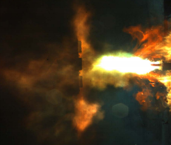
Arc Flash Event [1]
History
Using AFDRs is not particularly new, they have been around since the early 90’s. Back then, the optical cables were insulated and only detected light at the tip of the cable. These cables were focused on points and given the name point sensors. Today, a new type of fiber optic cable has been introduced which is uninsulated, allowing light to be received 360° along the entire length of the cable. These cables can be routed in a loop, which may be used to check the health of the system, making sure everything is functioning properly. These sensors are also able to detect ultraviolet light enabling it to react in the highest radiated energy wavelengths (200 nm – 600 nm). These two technologies can now be used together depending on the client’s needs. Fiber optic cable is primarily run along switchgear busbars while the point sensors monitor cubicles, buckets, panels, disconnects, etc.

Compatibility
AFDRs work best with equipment that incorporate interrupters that are SF6 or vacuum. This is because under a “normal” fault condition, these devices clear the fault within themselves. No light would be detected in this situation and if any light was detected by the sensor is due to an arc flash. In lower voltages and equipment, that use arc chutes (air magnetic breakers) the arc is broken down in air. This will change the ambient light conditions under normal fault clearing. Positioning of sensors is extremely critical to ensure a properly functioning system.
Some manufacturers have incorporated this technology into their own devices for added protection. Mersen makes a medium voltage controllable fuse, which is able to communicate with AFDRs. A traditional fuse on a transformer’s primary windings takes a considerable amount of time to react to an arc flash incident on the secondary. When using a programmable fuse, the fuse controller accepts an input from the AFDR that monitors the low voltage side conditions. When an event occurs, the fuse controller transmits a signal via a fiber-optic line to the fuse commanding it to redirect the supply current to an alternate smaller fuse that quickly opens in a controlled manner. This fast-acting process greatly reduces the amount of time required to clear the fault, which in turn, reduces the energy capable of being released during an arc flash.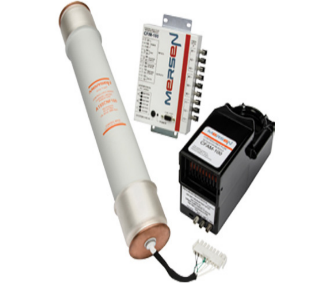
Mersen Controllable Fuse
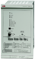
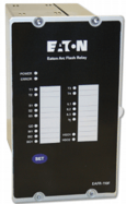
Since the technology has been around for a while, all major players in the electrical equipment industry have their own take on AFDRs as shown below.
|
Manufacturer |
Name |
Sample Unit |
|
ABB |
REA 101 |
|
|
Eaton |
EAFR |
|
|
Littelfuse |
AF0500 |
|
|
Schweitzer Engineering Laboratories |
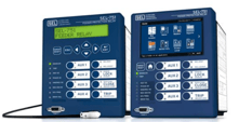
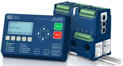
SEL-710-5/ SEL-751/ SEL-751A/ SEL-849 |
|
Conclusion
Since the devices are constantly monitoring light and current, they only trip when an event is occurring. Therefore, there is no need to worry about coordinating this system with the existing electrical system. The relays are entirely reactive and the main objective is to kill the source when an event occurs. If the optical cable is not used in a loop, it also becomes difficult to test the reliability of the AFDR system. The relay’s purpose is to extinguish an arc flash that is occurring. AFDRs are a great addition to any new or existing electrical system; it adds an extra level of protection in the event of a catastrophic accident. If an arc flash does occur, the quick response time of an AFDR system could save thousands in equipment costs, millions in downtime, and could be the difference between life and death. [2] [3]
References
|
[1] |
W.-J. Lee, Z. Zhang, S.-H. Rau, T. Gammon, B. Johnson and J. Beyreis, "Arc Flash Light Intensity Measurement System Design," IEEE Transactions on Industry Applications, vol. 51, no. 5, pp. 4267 - 4274, 2015. |
|
[2] |
R. Wilson, R. Harju, J. Keisala and S. Ganesan, "Tripping with the Speed of Light: Arc Flash Protection," in 60th Annual Conference for Protective Relay Engineers, College Station, TX, USA, 2007. |
|
[3] |
G. Roscoe, M. Valdes and R. Luna, "Methods for Arc-Flash Detection in Electrical Equipment," in Petroleum and Chemical Industry Conference (PCIC), San Antonio, TX, USA, USA, 2010. |
About the author
Chris Font has left Hallam-ICS to pursue other endeavors, but his contributions to the company continue to be valued.
Read My Hallam Story
About Hallam-ICS
Hallam-ICS is an engineering and automation company that designs MEP systems for facilities and plants, engineers control and automation solutions, and ensures safety and regulatory compliance through arc flash studies, commissioning, and validation. Our offices are located in Massachusetts, Connecticut, New York, Vermont and North Carolina and our projects take us world-wide.
You May Also Like
These Related Stories

Learning to Conduct an Arc Flash Survey

How to Read an Arc Flash Label





Comments (1)