
by Jon McClain on Apr 11, 2019 10:30:00 AM
I have recently gotten a few requests to help setup communication between an Allen-Bradley PLC and a B&R PLC. B&R Industrial Automation is becoming more popular in North America, as more OEMs are opting to go with the Austrian controls company recently acquired by ABB.
As a result, more end users are trying to integrate B&R machines into their mostly Rockwell plants. This guide describes the process of creating a connection between Allen-Bradley and B&R PLCs over Ethernet/IP using implicit messaging.
Hardware Setup
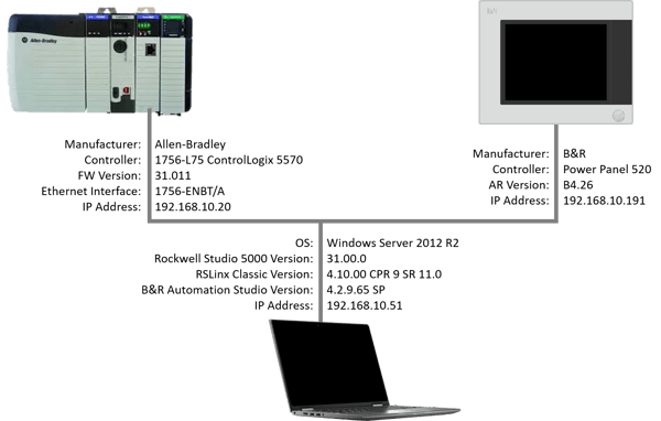 Figure 1: Test Ethernet/IP Network
Requirements
The end user must have the B&R source code, as well as the appropriate version of B&R Automation Studio software. Unlike Allen-Bradley, B&R programs cannot be uploaded from the controller by default. B&R programmers may choose to include the source code on a user partition of the compact flash card running the controller, but this option is rarely utilized.
- The B&R PLC must be of generation SG4, running Automation Runtime V2.00 or higher.
- The end user must have the appropriate Allen-Bradley software and the ability to download to the controller.
- The B&R PLC and the AB PLC should be on the same subnet.
A Bit about Ethernet/IP
Ethernet/IP is an industrial Ethernet-based network protocol that uses Common Industrial Protocol (CIP) for its upper layers of communication. For the sake of brevity, I will not dive too deeply into the nuts and bolts of Ethernet/IP. I invite you to visit the Open DeviceNet Vendor Association, Inc. (ODVA) website that will return a wealth of information on Ethernet/IP, CIP, and the OSI model, particularly within the Ethernet/IP Developer's Guide. While we will not go too far into detail on the networking side, it is important to understand some basic concepts and terminology before we get started.
One very important concept is the difference between the two main types of CIP messaging available to use over Ethernet/IP: explicit and implicit.
Explicit messaging is an asynchronous request/reply communication method that utilizes TCP/IP (response required) to achieve what is known as CIP transport class 3. This method is used mainly for slower or high-traffic networks to transfer higher-level time-noncritical data on an as-needed basis, like a client/server relationship. Explicit messaging requires the engineer to setup buffers and handshaking to direct when and where the data is read from and written to. This method can transfer much larger amounts of data but requires more upfront programming.
Implicit messaging is a synchronous communication method that uses UDP (no response required) to achieve CIP transport class 0 or 1. This method is used generally for lower-level time-critical operations, such as I/O communication. Think of this method as a scanner/adapter relationship. Implicit messaging transfers a smaller amount of data every network cycle and is setup more intrinsically as a hardware module than software.
In this example, we will be using implicit messaging to establish a connection between a B&R PLC and an Allen-Bradley PLC. There is an example program in the Help literature within Automation Studio, but we are going to build the connection from scratch.
Connecting To B&R As Ethernet/IP Device
On B&R Side
The first step in the process of setting up a B&R PLC as an Ethernet/IP device is to ensure that both the Allen-Bradley and the B&R are on the same subnet.
Create Data Object
B&R uses their AsEthIP library to establish implicit messaging over Ethernet/IP. The library requires a data object containing the connection configuration data. To create the data object in Automation Studio, go to the Logical View, right-click on a folder where you want the data object to be stored, and select Add Object. Select Data Object from the Toolbox Object Catalog:
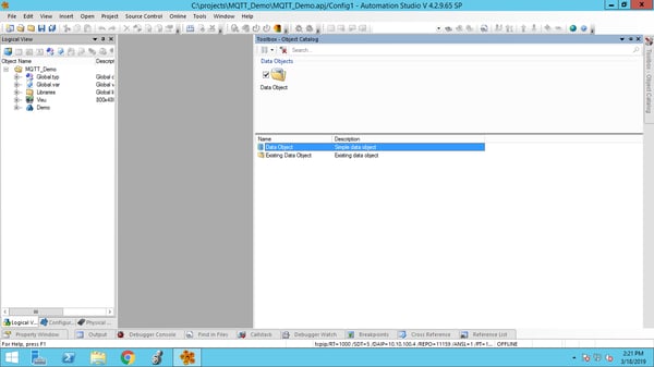 Figure 2: New Data Object in Automation Studio
This will add a blank data object. I renamed it EIPConfig.
You must setup the data object in a very specific format. This is the configuration for our example:
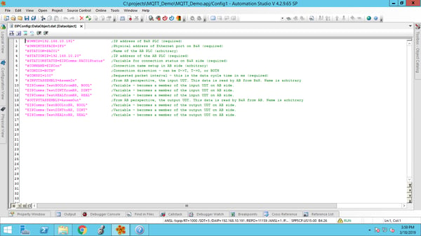 Figure 3: Ethernet/IP Configuration Data Object Syntax
Here are the configuration parameters and their explanations:
- #OWNIP The IP address of the B&R PLC. (Required)
- #OWNINTERFACE The physical address of the Ethernet port on the B&R side. (Required)
In this case, we’re using the ETH port, which is in position IF3:
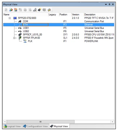
Figure 4: B&R Ethernet Interface Address
- #STATION The name of the AB PLC. (Required but arbitrary)
- #STATIONIP The IP address of the AB PLC. (Required)
- #STATIONSTATUS Assigns the status of the AB PLC to a variable on the B&R side. The value is the number of active Ethernet/IP connections to the originator. (Optional)
- #CONNAME The name of the connection. This will be used on the AB side as part of the add-on profile. (Required)
- #CONDIR Direction of the EIP connection. Can be O->T, T->O, or BOTH. Originator (O) is the AB PLC, and the Target (T) is the B&R PLC. (Required)
- #CONRPI Requested packet interval in ms. (Required)
- #INPUTASSEMBLY Does two things: 1. In ‘O->T’ or ‘BOTH’ connection directions, this creates the CIP transport class 0 assembly (#101) for inputs. 2. When using the auto- generate tool, this is also the data structure (UDT) used on the AB side for inputs.
- #OUTPUTASSEMBLY Like the input assembly, this does two things: 1. In T->O or BOTH connection directions, this creates the CIP transport class 0 assembly for outputs (#102). 2. When using the auto-generate tool, this is also the data structure (UDT) used on the AB side for outputs.
Below the assemblies are the respective variable declarations. The syntax for setting up variables in an assembly on the B&R side is:
Task:TagName, TagType, TagDim
For example, if I had a global variable called TestArrayREALs that was an array of 10 REALs, the syntax would be:
TestArrayREALs, REAL, 10
To keep it simple in this example, we have a BOOL, a DINT, and a REAL for both the Input and the Output assemblies.
You have to declare these variables in Automation Studio and they must be present in memory on the target, meaning that you must deploy these variables somewhere in code. When you use the GenerateL5k tool, the variables will be members of the UDTs on the AB side. It is also worth noting that the variables on the B&R side should not be a part of a data structure, as the configuration will just take the root. Once the data object is complete, add it to the software configuration.
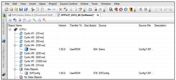 Figure 5: Data Object in Software Configuration
Create AsEthIP program in Automation Studio
Once the data object is configured and deployed in the software configuration, we must now create a cyclic program to run the Ethernet/IP driver using the AsEthIP library of functions. Add a new program from the object catalog. I chose to use a Structured Text all-in-one program:
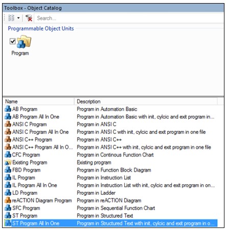
Figure 6: Adding New ST Program
I named my new program EIPComms to match what I designated for the program name in the data object. Now we have to create the local variables and function block instances in the local variable table: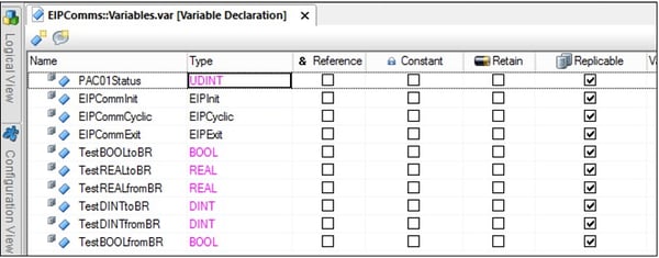
Figure 7: EIPComms Local Variables
Here is a layout of my code:
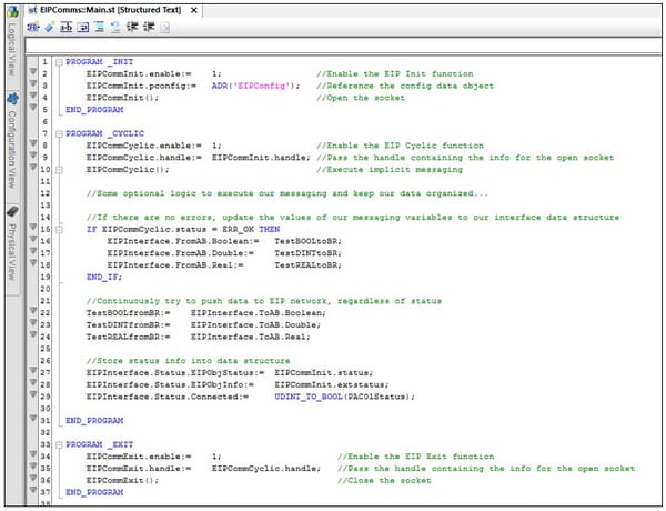
A few notes about this example code:
- The EIPCommInit.pconfig string should be the exact name of how the Data Object appears in the software configuration.
- I referenced all of the assembly variables declared in the data object. It makes the code cleaner to have the AsEthIP function block instances and assembly variables local to this program, but practically we will probably need to reference them in other places in the project, so I created the global EIPInterface structure to make a nice interface that we can use.
- The EIPCommExit function block instance is not a requirement, but it is useful at development time to close the socket. Otherwise, if you make a change to the program and flash to the PLC, the EIPCommInit function block will open another socket instead, and you will have to cycle power to get the communication to work properly.
- The variable PAC01Status is an unsigned double integer, with the value corresponding to the number of active CIP connections between the target and originator. Since Allen-Bradley limits this number to a maximum of one connection per IP address, I chose to cast the variable to a Boolean to tell us if we are connected.
- The Automation Studio Help has examples in Automation Basic as well as Structured Text.
Make sure that once the program is complete, it is deployed in the software configuration in a cyclic task class that runs at least twice as fast as the #CONRPI value in the data object. In this case, since we set the RPI to 100ms, the slowest we can run the program is 50ms.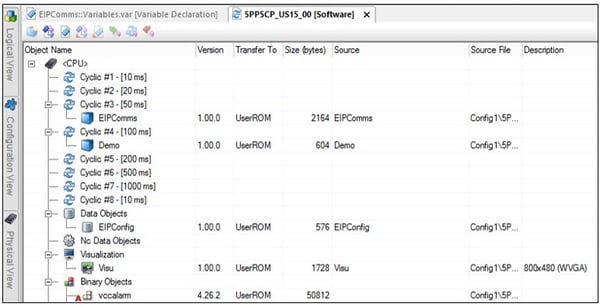
Figure 8: EIPComms Software Configuration Deployment
Now we can transfer to the B&R PLC. Below is a screen shot of my program in monitor mode. Notice that there are no configuration errors, but we are not yet connected: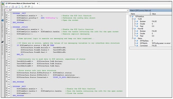
Figure 9: Monitoring of B&R Variables
GenerateL5k Utility
B&R has a tool that automatically generates the Ethernet/IP device along with some code that can be imported into Logix Designer. Since we are using AS4.2, the path to this app is:
C:\BrAutomation\AS42\Bin-en\BR.AS.GenerateL5k.exe
Launch the GenerateL5k tool, and select the target path by going to Options -> Target Path…
Once you select where the .L5K will be stored, select File -> GenerateL5k…
Browse to the Logical folder within the Automation Studio project directory to find the data object we created earlier. This is generally found in the following directory:
C:\projects\*name of project*\Logical\*name of EIP data object*
In our example, it is here: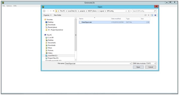
Figure 10: B&R GenerateL5k Utility
On Allen-Bradley Side
Once the .L5K file is generated, launch Studio 5000 as Create from Import. In Studio 5000, select the .L5K file (by default, it will be the name of #STATION in the B&R data object) and create a name and appropriate revision for the .ACD file.
Click OK to change controller type to what Logix Designer suggests, and it will generate a generic CompactLogix project with a Generic Ethernet Module. Notice the Module Properties Report: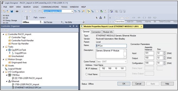
Figure 11: Studio 5000 Logix Designer Generic Ethernet/IP Module
The Name, IP Address, and the connection parameters all correspond to the B&R data object. Open the Controller Tags to see the tags corresponding to the data object: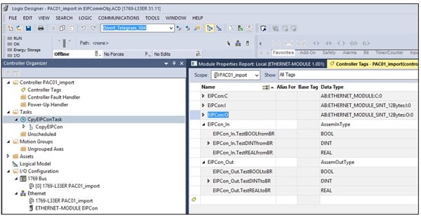
Figure 12: Ethernet/IP Module UDTs
The GenerateL5k utility also creates a task with a program containing routines that copy the input data from the B&R PLC to the EIPCon_In UDT and write data from EIPCon_Out to the B&R PLC. These tags and UDTs also came from the data object on the B&R system.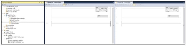
Figure 13: CpyEIPCon Routines
You do not necessarily have to keep these names for the UDTs or their members. The main thing is that the input and output buffers sizes line up with the assemblies in the B&R data object.
Copy and paste the ETHERNET-MODULE from the new project into the existing AB project PLC I/O Configuration, making sure to paste under the Ethernet/IP card on the correct subnet, in cases where multiple Ethernet/IP ports exist. Then copy and paste the CpyTask from the new to the existing project. Export the CpyEIPCon program from the new project and import into existing project under the CpyEIPConTask task. At this point, if you make any changes to the Ethernet/IP configuration, you have to modify the B&R data object first, then you can either use the GenerateL5k tool again, or you can manually change the assembly sizes or properties in the ETHERNET-MODULE properties (as well as sizes of the copy file function blocks in the routines of the CpyEIPCon program).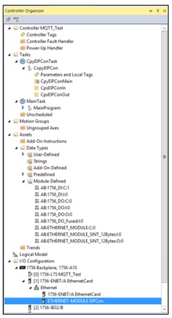
Figure 14: Existing Project with New Ethernet/IP Module
Download to the controller. If there are no problems, the Status will show Running in the Ethernet Module Properties Report. Change the value of a member of the EIPCon_Out UDT, and check to see if it showed up in the B&R side: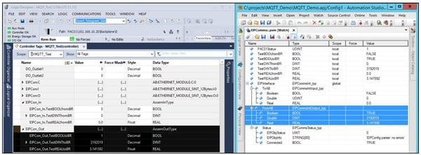
Figure 15: Test from AB to B&R
Then change values on the B&R side to see if they made it to the Allen-Bradley: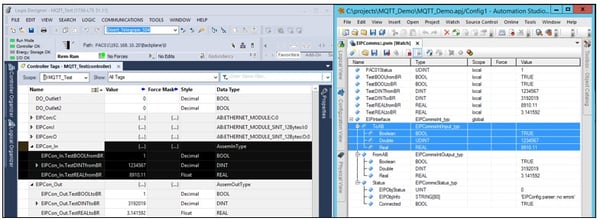 Figure 16: Test from B&R to AB
Congratulations, you have now setup B&R and Allen-Bradley PLCs to communicate over Ethernet/IP using implicit messaging.
At Hallam-ICS, we leverage our team’s technologically-diverse backgrounds to provide the end user with holistic and thoughtful process control and OT data solutions.

About the Author
Jon has left Hallam-ICS to pursue other endeavors, but his contributions to the company continue to be valued.
About Hallam-ICS
Hallam-ICS is an engineering and automation company that designs MEP systems for facilities and plants, engineers control and automation solutions, and ensures safety and regulatory compliance through arc flash studies, commissioning, and validation. Our offices are located in Massachusetts, Connecticut, New York, Vermont and North Carolina and our projects take us world-wide.

PLC5 to ControlLogix Conversions – Custom Solutions to Further Reduce Costs
Advancing Automation Technology - How to Specify a Domain Controller
Comments (4)