
by Dan Laird on Aug 21, 2018 10:32:00 AM
Background
The highest levels of arc flash energy are typically found at the secondaries of step-down transformers. This usually means the 480V main breakers, like the one shown above, will be over 40 cal/cm2. One method of mitigating this hazard is to install a manual reset recloser and digital relay on the primary side of the transformer. 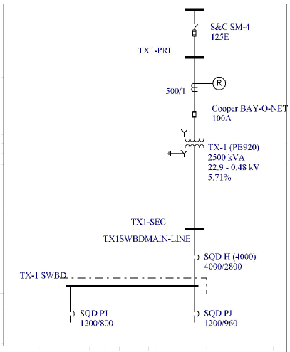
Recloser Relay on MV System for Arc Flash Mitigation
Programming these relays, however, is not intuitive since they use terminology that is more familiar to utility engineers than plant engineers. This blog will describe the key parameters of an SEL-351 (or SEL-651) in terms a plant electrical engineer is used to using.
Time Current Curves
Overcurrent Protective Device (OCPD) Coordination Studies use a graphical tool called a “Time-Current Curve” (TCC) to plot device opening times versus fault current. These TCC’s are used by engineers to make sure the devices closest to a fault trip before devices upstream. This is known as a well-coordinated system. An extreme example of a poorly coordinated system would be the popcorn maker blacking out the entire stadium because the local panel breakers have trip settings slower than the main breaker.
The TCC shown below shows a dark blue line representing the transformer damage curve for a 2500 kVA system. The orange and red areas are the fuse melting curves showing that they do indeed protect the transformer per ANSI guidelines and also melt open at times slower than the 480V main breaker. The fuses and the breaker are well-coordinated since they do not overlap.
To meet our arc flash goals, we need something that opens faster than the fuses but still not as fast as the 480V main breaker’s trip curve. We also want it to be slower than the transformer inrush point on the TCC so that we do not trip on energization. This is where the digital relay and recloser come in. Using standard power systems software, we can create the light blue trip curve shown below that meets our coordination and arc flash goals. The tricky part is converting the Tap, Time Dial, and Instantaneous nomenclature (based on electromechanical relays) into the proper parameters in the EZ-1 Menu of the digital SEL-351 relay.
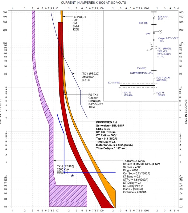
TCC for 2500kVA Transformer and Switchgear
SEL-351 Parameter Equivalents
The parameter for the Current Transformers (CT’s) is CTR in the SEL relay. In our example, the CT ratio is 500:1 so we can set CTR to 500. If the CT ratio had been 500:5, the CTR parameter would be 100.
In order to run the recloser trip curve parallel with the fuse melt curves, we selected a U2 or Inverse Curve. This can be selected in the SEL-351 relay under the DCPHASE parameter.
The Tap setting of 0.3 corresponds to 150A with our choice of CT. The same value in the SEL-351 would be achieved by setting MTPHASE to 150.

The Time Dial setting of 0.5 is TDDCPHASE in the SEL-351 and can also be set to 0.5.
The Instantaneous setting of 0.65 corresponds to 325A with our choice of CT. This can be set in the TDFCPHASE parameter as 0.65 (also FCPHASE of U2). Notice how this parameter is a multiple of current while MTPHASE is actual primary current.
We also want to add a 0.117 second delay to the relay to avoid the transformer inrush point. This can be achieved by setting the TDSEF parameter to 7 (7 cycles is equivalent to 0.1167 seconds on a 60 cycle power system).
The summary of SEL-351 EZ-1Settings to match our TCC are shown below.
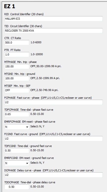 EZ 1 Phase Parameters from SEL-351
Conclusion
Our application allowed us to program the digital relay with just the EZ-1 Parameters. These top-level parameters affect many other parameters and should be changed with care. Different relays and more complex applications require more, even less intuitive parameters deeper in the database. However, digital relays are powerful tools for protecting electrical systems and collecting information. Our next blog in this series will look at tying these individual relays together into a Medium Voltage (MV) SCADA System. Meanwhile, check out my previous post on Medium Voltage Systems.
About the author
Dan Laird has left Hallam-ICS to pursue other endeavors, but his contributions to the company continue to be valued.
About Hallam-ICS
Hallam-ICS is an engineering and automation company that designs MEP systems for facilities and plants, engineers control and automation solutions, and ensures safety and regulatory compliance through arc flash studies, commissioning, and validation. Our offices are located in Massachusetts, Connecticut, New York, Vermont and North Carolina and our projects take us world-wide.
Ensure Data Integrity in cGMP: The Crucial Role of Validation Processes
5 Benefits of Infrared Thermography
Comments (1)