“I came across an iceberg last week” – Condensing Appliance Vents
by William Neuburger on Dec 9, 2021 10:27:14 AM
Condensing Gas Appliances
Condensing gas appliances (furnaces, boilers and water heaters) are those heating appliances which are designed to discharge low temperature combustion gas, increasing the energy efficiency of the heating operation. Manufacturers of condensing appliances indicate 95% or higher combustion efficiency. That efficacy is a consequence of taking more heat out of the combustion products and lowering their temperature low enough for the water vapor in the combustion gas to condense. The January 2018 issue of Engineered Systems magazine includes an article on the topic which goes into more depth than this blog post. Condensing oil appliances are less present in the market and in commercial sizes relatively new. This blog post does not address them, though their design and installation is like gas appliances.
Condensing gas appliances have been available for over 20 years as a commercially viable and reliable product. When deployed correctly, they serve their purpose well. The right applications for these appliances include indirect fired furnaces, low temperature heating (radiant ceiling panels, large European style panels, radiant floors or ceilings) domestic hot water, and snowmelt systems.
One of the consequences of using these appliances is the need to use suitable materials handling the combustion products and condensation (some refer to this as the vent or exhaust). These appliances demand corrosion resistant materials, often AL4-29C stainless steel, CPVC, PVC or polypropylene. The manufacturer’s installation guide will have specific requirements and installation practices covering maximum distance, pitch and supports. The installation guide will also describe pitching the vent back toward the appliance to minimize liquid water flowing from the vent terminal.
Codes
The local, statutory codes will also dictate installation requirements. Most jurisdictions adopt or modify either NFPA 54 National Fuel Gas Code or the International Fuel Gas Code. These codes are harmonious in their handling of condensing appliances. They both classify condensing appliances as either Category IV (positive vent pressure, below condensing temperature) or Category II (negative/nonpositive pressure, below condensing temperature). Category IV is the most common in our experience. They both also refer the designer or installer to the manufacturer’s instructions.
The vent termination location is critical to installation success for a condensing appliance. Conventional (Category I/III) appliance vents can often prescriptively follow the rules of NFPA 211 Chimneys, Fireplaces, Vents, and Solid Fuel–Burning Appliances. Condensing appliances require thoughtful considerations which are not prescriptive in the codes and manufacturer instructions. The specific rules governing location of the vent terminals require certain separation distances specifically to avoid walkways. The designer must think about the liquid water, where it will land and flow. Also, the designer must consider what hazards the inevitable winter season ice formations creates for the public and building tenants. Pitching the vent line properly toward the boiler minimizes liquid water leaving the vent, but the designer must contemplate the potential for liquid water.
A New Hampshire supply house produced a technician-focused technical paper covering venting which is dated, though applicable, which discusses in-depth the importance of draining liquid water from vents.
Venting
Through the roof venting can be an excellent way to manage the combustion gases, with respect to avoiding walkways. This method is not foolproof though. A project I designed in Watertown, NY included a group of condensing boilers and a combined stack with an outdoor chimney exhaust fan (our design included a new liner of the existing masonry chimney). During a power outage, the liquid water present in the vent and on the fan blades froze. The fan could not restart after power returned, causing a no heat condition. The owner resolved it with hair dryers and a heat gun.
Through the wall or sidewall venting is quite attractive to engineers and installers (my own residential boiler is sidewall vented). When contemplating this installation, imagine where liquid water will fall and where that liquid water will run, before freezing into ice. A great place to sidewall vent a condensing appliance is above gravel or some other pervious surface like a landscaping bed or grass. Some water will flow into the earth, the water that doesn’t will form ice. If the vent is in a landscaped bed or on a lawn, the ice should not create a hazard on a walkway. If using this approach, be sure to contemplate where the liquid water eventually flows, convince yourself the water will not cause ice on a nearby, downhill walkway.
The photo below is a commercial office building in Central Vermont. Not only is ice formation a danger to any who would approach the exterior basement stair, when the ice melts it flows down the stairs, creating an enhanced safety hazard when it freezes on the treads. Also, running water down the stairs increasing the exposure of the building’s architectural features to damage. It is likely the vent lines are not pitched back to the appliance.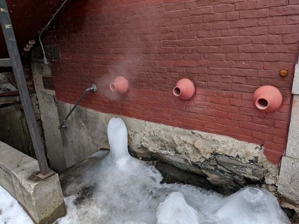
The picture below shows the ice from a condensing furnace air handler serving an office area in a mineral milling facility shipping center in New England. The products of combustion vent through the wall, above an outdoor mezzanine. The vent drips onto the air handler’s condensing unit. This installation offers little hazard to people as there is no cause to walk to this portion of the mezzanine, but this amount of ice on the condensing unit cannot be good for the unit’s longevity. There is another risk of the ice falling off the condensing unit in spring and potentially striking a passerby.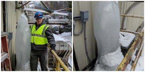
Sidebar – NFPA 54 Code Language
From the 2015 edition of NFPA 54, “12.9.4 Through-the-wall vents for Category II and Category IV appliances and noncategorized condensing appliances shall not terminate over public walkways or over an area where condensate or vapor could create a nuisance or hazard or could be detrimental to the operation of regulators, relief valves, or other equipment. Where local experience indicates that condensate is a problem with Category I and Category III appliances, this provision shall also apply. Drains for condensate shall be installed in accordance with the appliance and vent manufacturers’ installation instructions.”
About the Author
Bill has been a mechanical engineer since 1995 and with Hallam-ICS since 2010. His career has brought him to the top of the Transamerica Pyramid Center, chemical plants, underground mines, paper mills, and semiconductor fabrication facilities. He has experience designing, specifying and installing mechanical and electrical systems in the built environment covering industrial, institutional and commercial facilities.
Read My Hallam Story
About Hallam-ICS
Hallam-ICS is an engineering and automation company that designs MEP systems for facilities and plants, engineers control and automation solutions, and ensures safety and regulatory compliance through arc flash studies, commissioning, and validation. Our offices are located in Massachusetts, Connecticut, New York, Vermont and North Carolina and our projects take us world-wide.
You May Also Like
These Related Stories

FMCS: Boosting Reliability in Critical Facilities


Comments (1)