
by Thomas Toppin on Nov 19, 2019 10:46:00 AM
The beauty of the Library of Process Objects is that there isn’t much that the AOI’s cant do. Rockwell has done a wonderful job creating pre-canned logic that can account for almost every application. I’ll be the first to admit that sometimes it feels like overkill however knowing that all the features are available whether you use them or not is nice. Unfortunately there is a price to pay for all that functionality regarding scan times and memory usage so configuring your logix controller for optimal performance is critical. Rockwell goes into detail and lays out some best practices in chapter 3 of the PlantPAx reference manual.
Since every project is designed differently based on the application my intent isn't to tell anyone how to design their program. I would just like to point out a few of Rockwell’s suggestions that should be used as guidelines.
- Periodic tasks only must be used. It is recommended that the default continuous task is removed
- Typically 3 tasks created (fewer the better per the application)
- Fast Task (100 – 250 ms) used for discrete control (I/O)
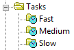
- Medium task (250 – 500 ms) used for flow/pressure loops/control strategies
- Slow task (1000 – 2000 ms) used for phases/batch sequencing
- Set up the “L_CPU” AOI to monitor controller utilization
- Try to limit the number of “CPS” instructions since they cannot be interrupted when a periodic task is called
- Total execution time of all the tasks should not exceed half the execution time of the slowest task
- Set the requested packet interval (RPI) two times faster than the task that it resides in
- Use program parameters to exchange data between programs and I/O. This simplifies I/O mapping and changes can be made online.
- Create user-defined data types (UDT) that contain all the data related to a specific activity. These can be used over and over which creates consistency for the programmer. They also have advantages regarding CPU resources.
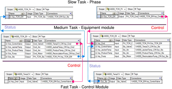
I know that it may be a little confusing as to how the fast/medium/slow task architecture works. Below is an illustration of a recent project that Hallam-ICS completed. Hopefully it will shed some light on how they all tie together. This example depicts a batch processing application where a jacketed tank (V4000) is required to maintain a certain product temperature within the tank. In this example we have a jacket temperature sensor, a product temperature sensor, a modulating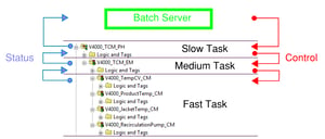 temperature control valve and a re-circulation pump. All of the programs for each of the devices would be added to the “Fast” task and appended with _CM (Control Module) to the program name. The control of all the devices is done in the “medium” task. This is where you would find the PID control and all the logic that would be telling the pump and valve what to do based on the vessels temperatures and SP. All the programs in the “medium” task were appended with _EM (Equipment Module) to the program name. The program in the “slow” routine is controlled by the batch server and appended with _PH (Phase). This is where commands from the batch server are received based on the recipe that is being used. When the recipe calls the temperature phase the desired temperature SP for the recipe is sent to the equipment module (medium task). The Equipment module controls the valve and pump to try an maintain the desired SP while monitoring the product and jacket temperatures coming from the control modules (fast task).
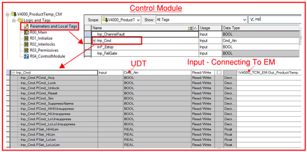
Each program communicates to each other through input / output parameters. When the equipment module sends commands to the control modules it is done using the user defined data types that Rockwell recommends. As an example here is the connection between the equipment module and the product temperature sensor control module. The connection uses a UDT we created called Cmd_Ain. It contains all the tags required to send commands to the control module. This data type resides in both the equipment module and control module. On the EM side it is created as an output parameter. On the CM side it is created as an input parameter.
![]()
The same strategy is used on the status side where the CM reports back to the EM. The EM would have an input parameter and the CM would have an output parameter of the same UDT. This strategy would be used for all CM’s and when communicating between phases and equipment modules as well. So in the example shown earlier the EM would have five output parameters (four for the commands to the CM’s and one for the status of the EM to the phase). The EM would also have five input parameters (Four for the status’s of the CM’s and one for the command coming from the phase).
Creating programs for each module, utilizing the periodic tasks as I have laid out and taking advantage of UDT’s will setup an architecture that is scale-able, repeatable and most importantly won’t cause controller performance problems. I can’t stress enough how important it is to follow all the guidelines Rockwell has laid out which will result in a truly dependable system. Following this structure will also pay off in regards to development time which I will get into in upcoming entries.
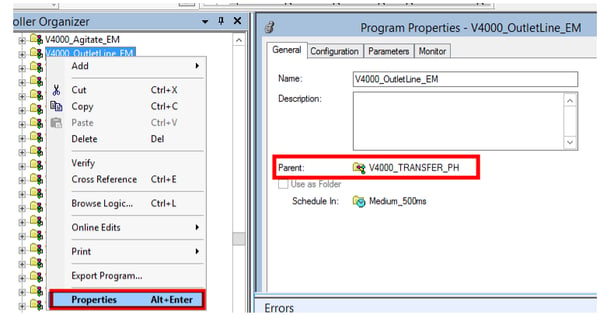
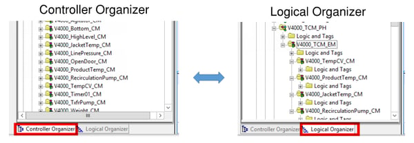
Another nice feature that Rockwell provides is the logical organization tab. Having multiple programs all related to different tasks can get somewhat unorganized especially with the scale of some of these projects. Luckily each program that you create can have a “parent folder” assigned to it. When you right click on the program, select properties and you can see which folder it is a member of.
If you want to change it’s parent folder you can simply click on it and drag it to any other folder you want by using the logical organizer tab. You can even create folders just for housekeeping purposes. In this example we have area folders that allow us to quickly find programs based on the area of the plant. If I want to quickly find logic related to the mixing tanks I can simply open the area folder we defined as “A03_Mixingarea” and I can easily locate what I need.
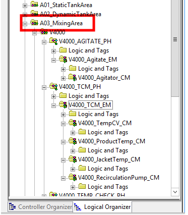
By creating this logical order you can actually begin to see the tasks and the prograaming structure that I discussed earlier. So instead of just seeing a bunch of programs listed by task in the controller organizer you can easly see what program is associated with each other.
Like I said earlier, each project is different and the programming structure will always be dependent on the application, I just wanted to share a few of the methods that I have learned in the past that have proven to be successful.
Another blog you might find interesting:
Programming with Rockwell Automation Plant PAx
About the Author
Tom Toppin is a Process Controls Engineer for Hallam-ICS. Tom started his career as an Electrician and has over 17 years’ experience designing, installing & troubleshooting electrical systems. Since becoming a Controls Engineer Tom has developed and commissioned a range of systems and his areas of expertise include continuous processing, batch processing, SCADA, water and wastewater.
Read My Hallam Story
About Hallam-ICS
Hallam-ICS is an engineering and automation company that designs MEP systems for facilities and plants, engineers control and automation solutions, and ensures safety and regulatory compliance through arc flash studies, commissioning, and validation. Our offices are located in Massachusetts, Connecticut, New York, Vermont and North Carolina and our projects take us world-wide.

Programming with Rockwell Automation's PlantPAx

8 Steps to Create an Electrical Safety Program Part 4
Comments (1)