
by Jeff Speroni on Mar 11, 2021 10:30:00 AM
So, VRF – What exactly is it all about?
Variable refrigerant flow (VRF) systems are air conditioning systems based around the vapor compression mechanical refrigeration cycle used to produce heating and cooling, similar to a standard direct expansion (DX) heat pump.What sets VRF apart? In a standard DX heat pump, there is a single refrigeration coil, connected to the condensing unit by refrigeration piping. The coil is inside of a sheet metal box, with a fan to blow air across the coil and produce conditioned air. That box is connected to the spaces requiring air conditioning by ductwork, and the fan pressurizes the duct system to move air into the occupied space. For VRF, rather than having a big box with ductwork running out to each space – each space has its own smaller sheet metal box with a smaller fan and smaller refrigeration coil. Instead of large ducts, we instead bring small refrigeration pipes from the outdoor unit to each indoor box.
Given that the VRF refrigeration system is spread across a larger footprint than the simple DX heat pump version, the VRF system is more custom engineered by the manufacturer. As a result, the system can be flexible and highly customizable. Modulating compressors are used, allowing for higher efficiency, in addition to limiting the fan energy required. VRF also takes up minimal space, allowing for easy retrofitting.
Air source VRF is popular around the globe with widespread use for 20+ years in Asia and Europe. Within North America, it’s steadily capturing a larger share of the residential and commercial market. A growing trend is the use of VRF in Passive House projects, or other projects seeking to reduce their site usage of fossil fuel. The latter is an especially hot topic these days, as many towns, cities, and even states are pushing for full electrification. The goal of building electrification being to transition all energy uses over to electricity only as the power grid moves to become cleaner and less reliant on fossil fuel. VRF can facilitate this goal by using an air source heat pump rather than a gas fired furnace or boiler. VRF is also a great fit when a project is spatially challenged, as small refrigerant piping can be snaked through a building much easier than larger sheet metal ducts.
What’s Right For My Project?
There are many different styles, manufacturers, and options for VRF. Each project is different and will need careful consideration to determine the best design. Cooling Only and Heat Pump Operation.
Cooling Only
Cooling only VRF is available and works the same as a heat pump (just without the reversing valve in the outdoor unit). Typically, these are used in the residential and light commercial marketplace. Think of the “mini-split” type units seen in homes, cafes, etc. Typically, these units are air source only. Some typical indoor units are shown in the following pictures as well.
- Key components: Indoor unit (evaporator), outdoor unit (condensing unit)
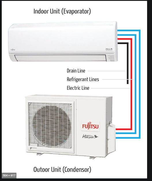
Figure 1: Cooling only VRF System (Fujitsu website)
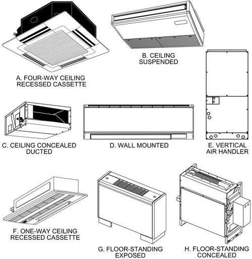
Figure 2: Common VRF Indoor Unit Types (ASHRAE Systems and Equipment 2020, Ch. 18)
Heat Pump
Provides heating and cooling, but both options are not available simultaneously. Again, this will look very similar to the cooling only options. Air source and water source heat rejection options are available, but air source is most common.
- Key components: Indoor unit (evaporator), outdoor unit (condensing unit)
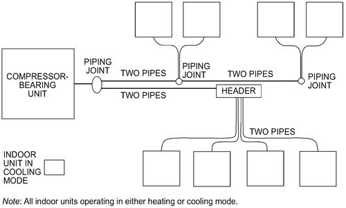 Figure 3: Heat Pump VRF System Diagram (ASHRAE Systems and Equipment 2020, Ch. 18)
Heat Recovery
This is the category where VRF really shines and provides the most versatility for the built environment. It’s also the most complicated to design. Heat recovery VRF provides heating and cooling, with both options available simultaneously. Air source is the most common option, but water source is also available.
- Key components: Indoor unit (evaporator), outdoor unit (condensing unit), heat recovery control unit (within the condensing unit, usually), branch selector box (see the diagram below, “sub heat recovery control unit”). “2 pipe” vs. 3 pipe: Refers to number of refrigerant pipes from outdoor unit to branch selector boxes. Ultimately, both systems require a 3rd refrigerant pipe at one point to facilitate heat recovery, see diagrams below. Both options are available in the marketplace but depend on the manufacturer.
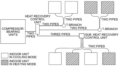
Figure 4: 2 Pipe VRF Heat Recovery (ASHRAE Systems and Equipment 2020, Ch. 18)
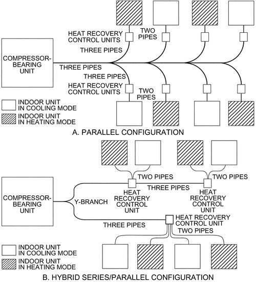
Figure 5: 2 Pipe VRF Heat Recovery (ASHRAE Systems and Equipment 2020, Ch. 18)
VRF Design Recommendations and “Gotcha’s”
Need to Design Bottom Up, Instead of Top Down
The typical workflow an HVAC design is to estimate size of key central components (chiller, boiler, cooling tower, etc) based on preliminary block loads within a space and develop the space by space design as the project progresses and those spaces are further refined. VRF requires the opposite approach. To properly size the outdoor units, all indoor units must be defined first. So, a space by space load calculation must be done, desired zoning determined, indoor units selected, and then finally outdoor unit design can be determined. This is due to refrigerant charge limitations, oil return, branch selector box capacities, and ASHRAE standards 15 and 34 requirements. Most outdoor units have a capacity requirement of approx. 70%-150% of connected indoor units.
Indoor Unit Design Considerations
- Consider proper indoor unit(s) to meet space thermal loads, and an acceptable appearance to meet architectural requirements.
- When in heat pump operation, careful planning/grouping of indoor units must occur for zoning purposes.
- In heat recovery operation, indoor unit grouping is a function of the “branch box” – boxes have maximum numbers of indoor units that can be connected, and maximum piping limitations; define which zones must be able to have independent operation.
- Refrigerant Charge: be wary of ASHRAE 15 requirements. Refrigerant used in VRF is not acutely poisonous but is an asphyxiant as it will displace breathable oxygen from a space. Transfer grilles can be used to group rooms together, increasing the volume of a space and reducing concentration of refrigerant during a leak. It is critical to consider this early in a project, and for the design team and manufacturer to coordinate.
Outdoor Unit Design Considerations
- Most manufacturers have a “maximum” individual outdoor module – to achieve outdoor units above a specific capacity, manufacturers simply manifold these units together.
- Outdoor units and indoor unit piping lengths, and height relationship is critical. Air source and water source are both typically limited to around 150 ft elevation between outdoor and their corresponding indoor units.
- Like other devices rejecting heat to air, layout of outdoor units must allow for proper airflow and serviceability.
- Note that in situations where outdoor units are stacked vertically – provide means to drain each unit without splashing on the unit below. A sheet metal pan directing water flow away from the unit below, for example. This is especially important for winter operation, as defrost cycle induced melting needs to be directed away from units below to avoid creation of rooftop icebergs.
- All outdoor units do not need to be in one central location. This is an especially common configuration in Europe and Asia residential high rises.
- A small “outdoor” mechanical area is provided with a louvered face or exposed outdoor units.
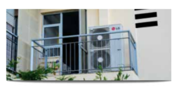
Figure 6: Air Source VRF Outdoor Unit on Porch (LG Website)
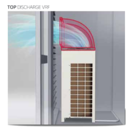
Figure 7: Enclosed Air Source VRF Outdoor Unit
Consider the Geographic Region
Specific options must be selected for proper operation in particularly cold regions. This is especially important as we travel from the Hallam-ICS Southern New England office up to the South Burlington, VT office. (Southern New England counts here, too, not just you folks up in Vermont!). This will influence heat recovery vs heat pump, in addition to specific accessories required.
Low ambient heating packages can be provided to allow for heating operation below 0°F (see Daikin VRV IV or Mitsubishi Hyper Heat option). The Designer needs to be aware that defrost cycle will reduce capacity – outdoor unit design to be reviewed to make sure that the de-rated capacity of the unit at design weather conditions can meet peak loads. (Heating capacity reduced by about 25% at -13°F compared to nameplate).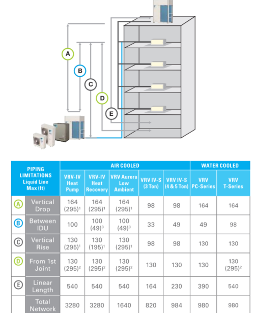
Figure 8: VRF Piping Limitations (Daikin VRV Reference Guide)
VRF can be utilized across many different building types and occupancies. It’s share of the market is only going to increase as the AEC industry pushes towards electrification. It’s among the most energy efficient options for providing heat via site electricity only.
Here at Hallam-ICS, we love to design for the unique, “oddball” situations. VRF is a great tool we can utilize to fit the space heating and cooling needs for those unique designs. We’ve explored installing outdoor VRF units inside of a warm pump room and using them for as a simple means of recovery of low-grade heat – transferring heat that would otherwise be exhausted out the building. VRF can be utilized in tandem with a DOAS unit in labs to provide space heating and cooling, minimizing the outside air that must be conditioned. If the project space is critical and the associated heating and cooling must be on generator power – what do you do if the central boiler/chiller plant isn’t? VRF is a great option in that situation to avoid a potentially significant electrical upgrade project.
About the author
Jeff joined Hallam-ICS in April 2020. He joined as a Sr. Mechanical Engineer, and has a strong technical background in building mechanical systems and MEP/FP project management.
Read My Hallam Story
About Hallam-ICS
Hallam-ICS is an engineering and automation company that designs MEP systems for facilities and plants, engineers control and automation solutions, and ensures safety and regulatory compliance through arc flash studies, commissioning, and validation. Our offices are located in Massachusetts, Connecticut, New York, Vermont and North Carolina and our projects take us world-wide.

Are Electric Vehicles the Wave of the Future?
Why Hallam-ICS Partnered with VST Engineering for ANTIDET Systems
No Comments Yet
Let us know what you think