
by Jason Barry and Dalton Sheehan on Aug 12, 2021 10:30:00 AM
Overview
In this blog, we will explore the basics of how Inductive Automation’s Ignition SCADA works. This includes the underlying services, software modules, and system architectures that Ignition employs. Let’s look at the fundamentals of how Ignition works.
Three Underlying Services
Before you dive into Ignition, it is important to understand how the three different Ignition services are split up:
The Gateway
- Primary Ignition service.
- Web server that hosts your project.
- Manages data collection.
- Contains server configuration and statistics.
The Designer
- Downloaded from the Gateway to any computer.
- Used to configure screens and tag data to create your project.
The Client
- Runtime view nodes of your project.
- Can be run on any computer via web browser.
- Displays the project screens made in the Designer.
Think of the gateway as the central server through which all data flows in your system. This server hosts the web-based clients and allows the user to download the designer when they need to make changes to a project. Having this diversification of roles may seem confusing at first but Ignition seeks to remove the barriers to access that so many SCADA software have, both for view nodes and development nodes.
By allowing any tablet or phone to be a client and any computer to be a designer, Ignition removes the technological constraints that have prevented SCADAs from being used more often, in a broader range of circumstances, and by a more diverse group of users.
Software Modules
Ignition is built on a modular system with each module providing a specific functionality that can be added on to the base Ignition platform. They are used to tailor your project to accomplish a specific need or requirement. All Ignition Modules can be installed, deleted, and upgraded without impacting your project or interfering with other modules you may have previously installed.
The Ignition Core Modules will allow you to create a fully capable project with:
- Screens for both plant-floor and mobile-first applications.
- Full SQL database access.
- Tag historian capabilities.
- Admin installation management.
- Advanced alarming and reporting functions.
- Core drivers for most major PLCs and communication protocols.
- OPC UA server
Ignition is the first system that doesn’t require a third-party OPC-UA server to connect to outside devices. Each of the nine Modules that allow these functions are referred to as “Ignition Core Modules” and should fulfill most applications.
However, Inductive Automation also offers a variety of non-core modules. These modules can be enabled to provide additional functionality beyond the core modules:
- Sequential Function Charts (SFC) Module
- Web Browser Module
- OPC COM Module
- Voice Notification Module
- SMS Notification Module
- Twilio Notification Module
- Web Development Module
- Serial Module
- SECS/GEM Module
Most Modules are self-explanatory. OPC COM allows you to use COM protocol to communicate with older devices. Voice/SMS Notification implements either robotic text-to-speech voicemail or text message to cellphones. Twilio Notification integrates Twilio SMS text with Ignition. The Serial Module adds serial comm support and new functions to scripts.
But some Modules such as the Web Development, SFC, SECS/GEM Module and Web Browser Module could use more explanation.
Web Dev
Web Dev allows you to program against the Gateway’s and Vision Client’s web server. This takes more knowledge than the standard SCADA programming expertise, but it is an option for web developers and those who wish to integrate a webpage more deeply within their project.
Sequential Function Charts (SFC)
The Sequential Function Charts (SFC) Module allows the programmer to use the visual logic of a sequential function chart to add even more flexibility to a project. The visual component added to the project’s main screen allows simple drag and drop programming that can further decrease development time, especially if a programmer is not familiar with Python. Similar to Python scripting, the logic in this Module can run for the duration of your projects lifespan by using shutdown and startup commands to pause and resume your program. SFC also supports redundant project setups and can be edited while it is active.
SECS/GEM Module
This Module modifies the Ignition Gateway and adds components to specifically communicate with semiconductor fabrication equipment. With these added components you can manage:
- Equipment
- Module Settings
- Simulator
The equipment header is where you set up device communication (either ethernet or serial) and configure the SECS messages into your database. The simulator allows you to virtually modify or add new devices and test them in your project without actually changing the hardware.
Web Browser
The Web Browser Module is simple, it places a web browser within the Designer that can be accessed from the Client. You can embed any permitted webpage or local intranet site to your project. Thanks to Chromium, Ignition’s web browser supports HTML5, CSS, and JavaScript.
System Architecture
It is important to define your network architecture at the start of project development. If set up incorrectly, there could be unnecessary downtime due to restructuring a network in the future. Luckily, Ignition has a very modifiable architecture, so it can fit your application even as your application grows and changes. Here is a list of possible Ignition system architectures:
- Standard
- Hub and Spoke
- Scale Out
- IIOT
- Enterprise
- Redundancy
- Cloud Based Architectures
This list is not exhaustive and there are some cases where you may choose to mix and match architecture design elements to match your need. Let’s take a deeper look at a few of the common and not-so-common architectures that your company might choose.
Standard Architecture
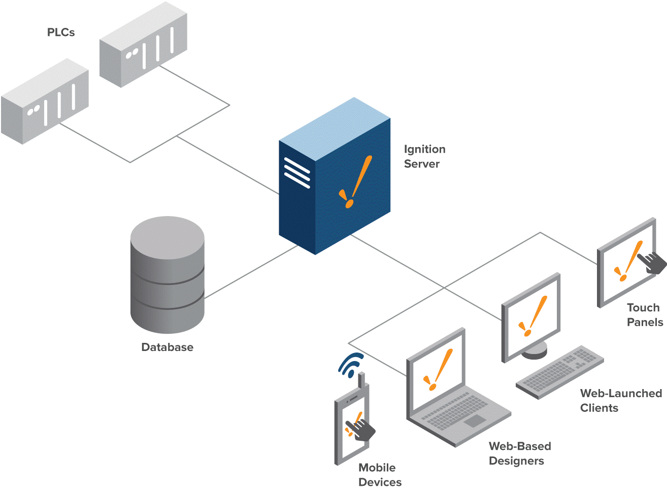
Image source: Inductive Automation
The standard architecture is the most basic way to setup an Ignition server. But even with the standard architecture, you can launch as many Clients from the Gateway as needed. You can even setup the Gateway with multiple networks thanks to Ignition’s dual-NIC server capability. This allows you to bridge between multiple networks or sites over a corporate WAN.
It is important to remember that all PLC and database data goes through the Gateway to reach the Client(s). This allows Clients to be launched from either your own corporate network or an isolated control network.
Hub-and-Spoke Architecture
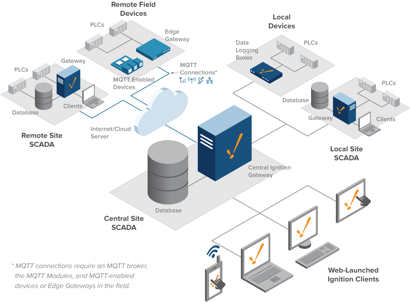
Image source: Inductive Automation
Hub-and-spoke architecture can be thought of as a tree where the trunk is a centralized Ignition Gateway and each branch are other Ignition installations that need to pass data to the trunk. Each branch communicates with the centralized Gateway and can forward data to it for processing.
A hub-and-spoke architecture can be the right choice if you have multiple sites but want to be able to view data from all sites at a central location.
Scale Out
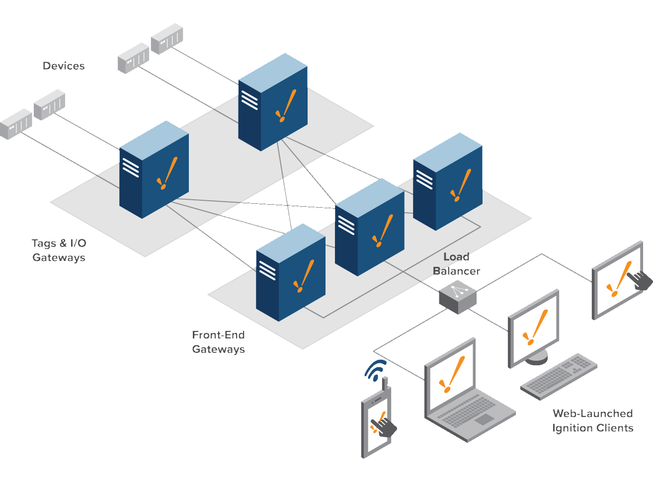
Image source: Inductive Automation
Scale Out fulfills a similar role as a hub-and-spoke layout but is designed for a single very large system that isn’t split into different sites. A major advantage of this layout is the ability for it to grow with your system. Gateways have more segregated roles with some gateways managing tags and IO communication while others manage the distribution of that data clients. More gateways can be added as you increase the number of clients or devices your system contains.
Load balancers can also be added to evenly distribute the Clients between Gateways. This increases the efficiently of network traffic and automates what is often a manual task.
You can tweak how each Gateway is assigned by either setting it up as a Back-End Gateway or a Front-End Gateway.
- Back-End Gateways are more concerned with connecting to tags and I/O. They share their local tags with the Front-End Gateway with a Remote Tag Provider.
- Front-End Gateways are responsible for the distribution of data to the clients, which allow the Back-End Gateways to solely support communication to devices on the plant floor.
IIoT Architecture
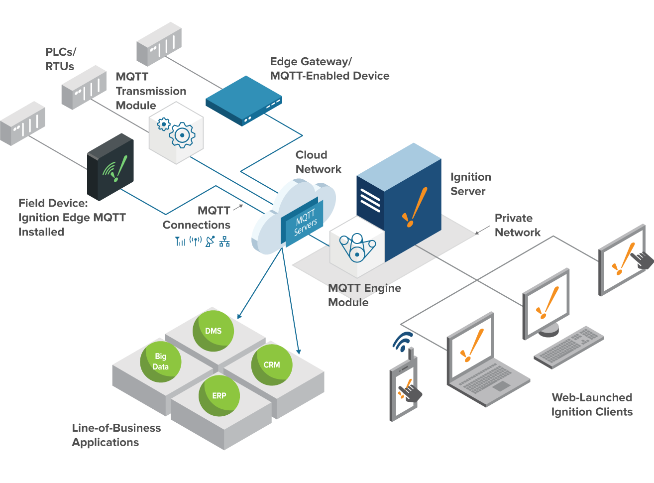
Image source: Inductive Automation
IIoT Architecture utilizes Ignition’s MQTT Transmission Module to connect to PLCs.
With a connection to a MQTT broker from either hardware, with Ignition Edge MQTT, or MQTT enabled Gateways that use the Cirrus Link Sparkplug MQTT specification, the Ignition Gateway can connect to data that is published by the broker.
It is important to understand that the MQTT protocol is just a publish/subscribe communication protocol that can connect to many devices at once. For the IIoT architecture to work it needs to have a Field Device, a MQTT Server (Broker) and a Subscriber:
- Field Device – Needs to connect to a PLC and publish tags values to a MQTT server (Ignition Edge with MQTT plugin or server with MQTT Transmitter Module).
- MQTT Server (Broker) – A Server to communicate to the Field Device (Ignition Gateway with the MQTT Distributor Module).
- Subscriber – The application to subscribe to the Broker’s topic (Ignition Gateway with the MQTT Engine Module).
Enterprise Architecture
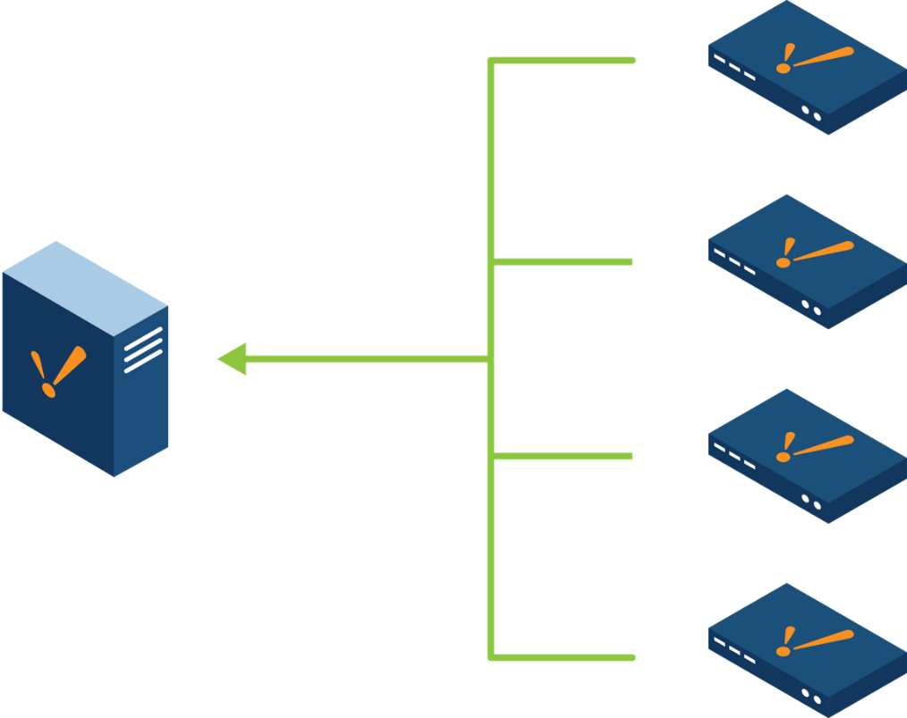
Image source: Inductive Automation
Enterprise Architecture can be used when you want to monitor and manage multiple Ignition servers in your setup. You need to install the Enterprise Administration Module in order to utilize this architecture. When the Module is installed you have the option to set one Gateway as the Controller and any other project Gateways as Agents.
The advantage of using this Module is the ability to monitor the overall health of several different systems at once. Instead of having to check each one manually, the central Controller Gateway can report a fault or problem from all the other agents.
Redundancy Architecture
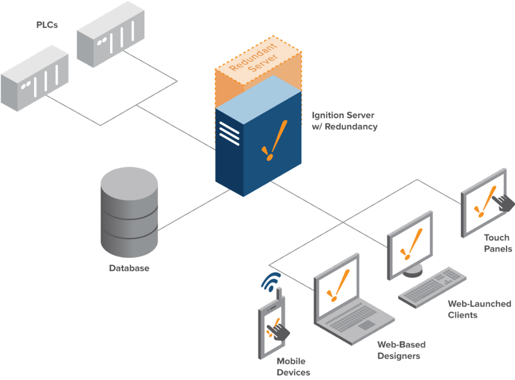
Image source: Inductive Automation
Redundancy Architecture is self-explanatory. It utilizes two Ignition installations with one server running the active project and the second ready to take over if the first one fails.
Once you setup redundancy, if the fist server fails, all the Clients will be redirected to the second server automatically. The backup server can also continue to log historical data seamlessly.
Ignition redundancy can be added to any type of system architecture. But it is only recommended to use it on a Cloud Based Architecture if its built-in redundancy delay time does not match your requirements.
Cloud Based Architecture
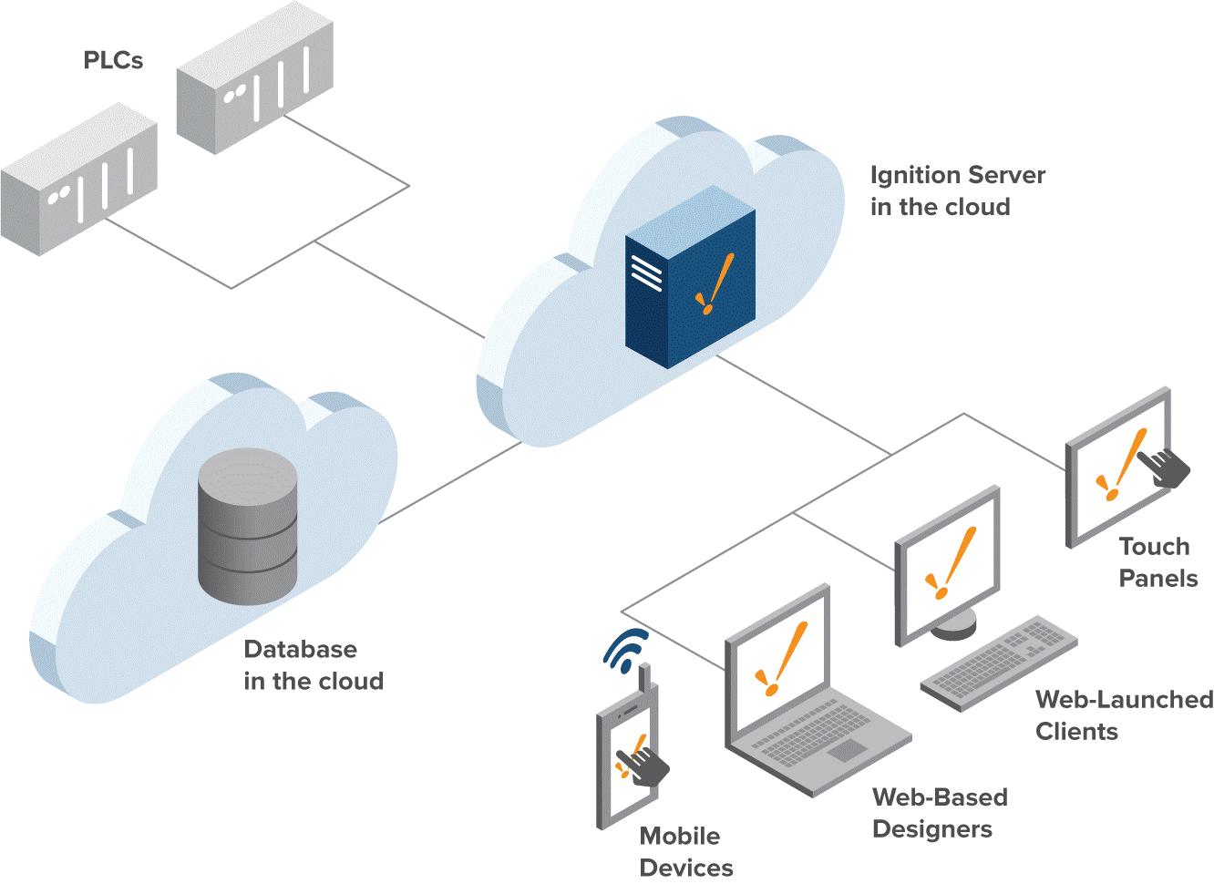
Image source: Inductive Automation
Cloud Based Architecture is great if you have a smaller organization that isn’t equipped to maintain a server.
Cloud could theoretically be implemented into any other architecture, but you may want to consider the cost before doing so. When you do setup the cloud structure, it is common to have your server and database on separate clouds. This separation creates better project security and management.
It is also possible to setup both local and cloud databases if you want them to serve different functions. A local database could be used for temporary or in-progress data calculations while the cloud could service everything else.
About the authors
Jason Barry is a Controls Engineer for Hallam-ICS. He has spent his career working on process automation systems in a variety of industries including Chemical, Food and Beverage, Oil and Gas, and Toxic Gas Monitoring. His area of expertise includes Rockwell PLCs, multiple SCADA software, and SQL databases.
Read My Hallam Story
Dalton Sheehan is a Controls Engineer for Hallam-ICS. He is one of the younger hires but has a strong background in the pharmaceuticals industry mainly focusing on compliance integration and OEE studies.
Read My Hallam Story
About Hallam-ICS
Hallam-ICS is an engineering and automation company that designs MEP systems for facilities and plants, engineers control and automation solutions, and ensures safety and regulatory compliance through arc flash studies, commissioning, and validation. Our offices are located in Massachusetts, Connecticut, New York, Vermont and North Carolina and our projects take us world-wide.

Advancing Automation Technology - How to Specify a Domain Controller

Data Sources and Transactions for Manufacturing Intelligence

No Comments Yet
Let us know what you think