
by Joshua Felgate on Mar 28, 2024 11:30:00 AM
Performing an arc flash hazard analysis saves lives but performing one accurately will save many more. It is vital during the calculations of incident energy that the person or persons performing such an analysis understands the causes of high incident energy and the methodologies NFPA 70E and IEEE 1584 utilize for determining such values. Rushing headlong into an analysis without this understanding will lead to miscalculated incident energies, underestimated arc flash hazards, and potential loss of life. It is my intention to give insight into a common misconception that can have such an impact, and it is my hope that through education there can be hazard prevention.
The misconception in question is the idea that a maximum fault current, calculated by the infinite bus method, is the most conservative estimate for arc flash hazard analysis. However, this can prove to not be the case. This blog will cover what the infinite bus method is, the impact it has on arc faults, and why it should not be used as a catch all for worst-case scenarios.
What Is Infinite Bus?
When Hallam-ICS conducts an arc flash hazard analysis, a request is sent to the utility company for the site in question. Typical information sought after includes the actual fault current contributed by the utility company (often in amps or per unit values) and transformer information such as kVA, primary and secondary voltages, and percent impedance. Utility companies will ideally supply this information and more, but sometimes they instead provide only the transformer information and a maximum fault current.
To identify whether the utility company supplied actual fault current or an infinite bus calculated value, one must only know the equation used to find a theoretical maximum fault current. The equation involves identifying the full load amps of a transformer and dividing it by the impedance. For example, let’s determine the maximum theoretical fault current of a site with a 750 kVA transformer that has a 480V secondary and an impedance of 5.75%. We can first calculate the full load amps of the transformer: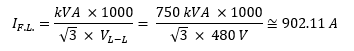
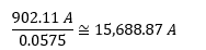
Dividing the resulting value by the %Z of the transformer gives the theoretical maximum fault:
Evidence of this can be seen by comparing our derived values to those obtained through software calculations. This one-line diagram shows the result of modelling the transformer in SKM PowerTools, a common program utilized for arc flash hazard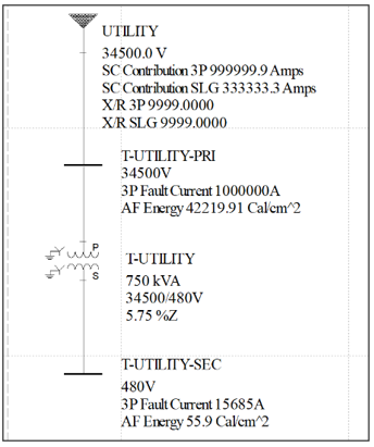 analysis. In this example, the utility at the transformer primary is given a voltage and is set to provide an infinite bus. To accomplish this, SKM situates itself to input 999,999.9 amps of three-phase fault current into the primary side of the transformer, a value far beyond what would likely be seen in real world applications. By this, it becomes apparent where the name “infinite bus” comes from. As the amount of current SKM supplies to the primary side of the transformer gets infinitely high, it will approach our derived value. This simulated transformer gets up to 15,685 A, which is within 0.02% of our previous derivation.

The Relationship Between Infinite Bus and Arc Flash
While not ideal, the infinite bus method is still a useful tool in identifying hazards. For example, if you were working on a site that has never had a comprehensive arc flash study performed and had no warning labels, you would need to utilize NFPA 70E Table 130.7(C)(15)(a). This is a tool for determining the necessary PPE for AC systems in a situation where the incident energy of the system has yet to be calculated. It is in this table that maximum available fault current can become correlated with arc flash hazards, as it is used as a parameter for determining Arc Flash PPE Category.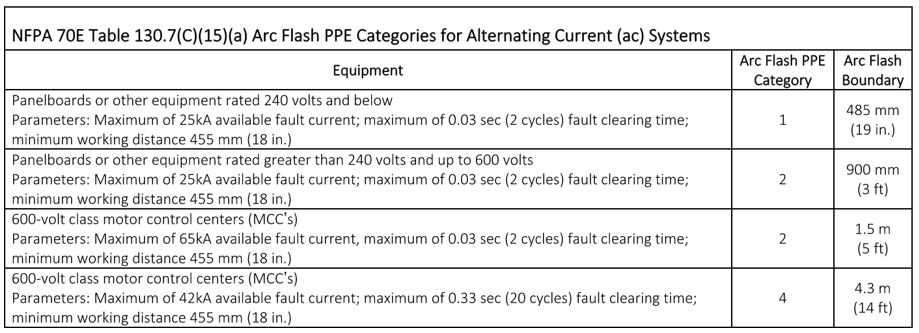
The same table also gives credence to the idea that maximum fault current is not everything when it comes to the hazards of arc flash. Looking at the PPE Category for 600-volt class motor control centers (MCC), it’s apparent that an MCC with a higher maximum available fault current of 65kA but a shorter fault clearing time of 0.03 seconds requires Category 2 Arc Flash PPE while the lower maximum fault current of 45kA with a longer 0.33 second fault clearing time calls for much more protective Category 4 Arc Flash PPE. It is incredibly important to be aware of this: a higher maximum fault current does not correlate with worst-case scenarios, and the effect of fault clearing time cannot be understated.
Where Maximum Fault Current Falls Flat
To further explore the impact of fault clearing times on incident energy, let’s dive back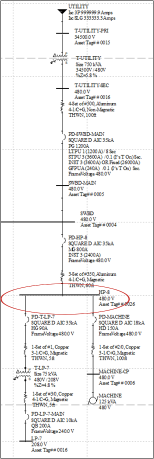 into the aforementioned distribution used to test out the infinite bus calculation. We left off determining that the secondary side of the transformer will have a maximum available fault current of 15.69 kA. Now, observe the relationship this has with the downstream equipment. We can take a typical configuration of a power system and add it onto the distribution. In this situation, careful attention is going to be paid to the incident energy of panel “HP-8”.
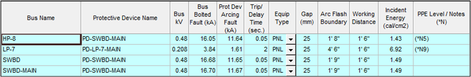
Currently, if an arc flash evaluation was performed utilizing infinite bus on the transformer primary, the panel would have an incident energy of 1.43 cal/cm2, as seen below in the “Infinite” bus summary taken from SKM (refer to the “Infinite Bus/Maximum Fault Current” Table). This is not considered a particularly dangerous incident energy, just cresting the threshold to require more than the minimum amount of PPE. However, more details show that a fault occurring at HP-8 is protected by the main breaker of the switchboard instead of the one feeding the panel. The bus summary also shows that this main breaker has a fault clearing time of 0.05 seconds. All of this is the case when the system is supplied with the highest fault current theoretically possible based on the primary infinite bus approach. But what if that was not the case? What if the utility company offered the maximum available but the actual fault current seen at the transformer was only 20% of that? At a fault current of 3.14 kA on the secondary side of the transformer, a significant change occurs.
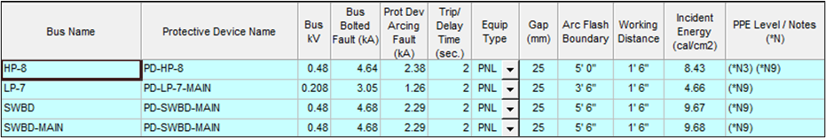
Now, looking at the “20%” bus summary (refer to the “20% of Maximum Fault Current” Table), it is apparent that the condition for HP-8 has changed, now rated for an incident energy of 8.43 cal/cm2. Where it once was protected by the main breaker, it is now protected by its own feeder breaker, and where it once had a fault clearing time of 0.05 seconds, it now trips at 2 seconds (It is worth noting that the 2 seconds is not the actual trip time but rather an arbitrary number, accounting for the time and ability of oneself to leave the area in case of any arcs). The current is low enough that the breaker for HP-8 may not trip for a full 60 seconds, making the panel far more dangerous at 20% of the maximum fault current than at the maximum itself.
Infinite Bus/Maximum Fault Current
20% of Maximum Fault Current
This is precisely why it becomes important for the engineer performing an arc flash analysis of power systems to be fully aware of the complexities with calculating incident energy. If someone was operating on this panel and the fault was sustained for the full 62.953 seconds it would take for the breaker for trip, the chances of survival are slim to none should something prevent them from getting away.
I know this example seemed convenient to prove a concept but do not be fooled by the appearance. What if I told you that this is representative of a real site that Hallam-ICS performed an arc flash analysis on? Everything in the examples was taken directly from the actual maximum fault current supplied by the utility company and from the power system as Hallam-ICS surveyed it. From the transformer size and impedance to the tripping characteristics of the breakers, this is a real-world example of what could be missed when mistakenly correlating maximum fault current with a worst-case incident energy. When dealing with safety and risk to life, Hallam-ICS understands the importance of good engineering practices and detail-oriented analyses.
This is not meant to advocate against the use of the infinite bus method in power systems. If you were to be just looking for maximum possible fault current of a building system to determine what the distribution equipment should be braced for, utilizing the infinite bus method to calculate maximum fault currents would be an acceptable, conservative approach for determining the required equipment AIC ratings. However, as the example provided shows, pursuing the actual available fault current from utility companies is not only the right approach, but a necessary approach for providing the appropriate information for determining the minimum PPE equipment someone should wear when servicing, maintaining, or operating distribution equipment when the equipment is energized.
About the Author
Joshua Felgate is an Electrical Engineer at Hallam-ICS experienced in Power Systems Studies and Arc Flash Analysis. He has a B.S. in Electrical Engineering as a 2020 graduate at Liberty University. He is a lover of both film and trashy reality TV, enjoys cooking and the occasional artistic endeavor.
Read My Hallam Story
About Hallam-ICS
Hallam-ICS is an engineering and automation company that designs MEP systems for facilities and plants, engineers control and automation solutions, and ensures safety and regulatory compliance through arc flash studies, commissioning, and validation. Our offices are located in Massachusetts, Connecticut, New York, Vermont and North Carolina Texas, Florida and our projects take us world-wide.


Metrology and Calibration - Weights and Measures

Why Gas Monitoring Should Never Be Together with Gas Cabinets, And, Why Gas Monitoring Should Always Be Together with Gas Cabinets

No Comments Yet
Let us know what you think