
by Scott King, PMP on Jun 17, 2021 10:30:00 AM
Hallam-ICS provides electrical safety, design, and mitigation services to our clients. We also try to share our knowledge through blogs, white papers, and webinars to help educate electrical and safety professionals. I have written this series of blogs to provide more information about Infrared Thermography. The four blogs in this series are:
- Infrared Thermography for Electrical Equipment
- Why is Infrared Thermography Important for Electrical Equipment?
- Electrical Equipment and Challenges with Infrared Thermography
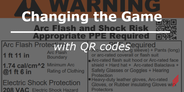
- The Benefits of Combining Infrared Thermography with an Arc Flash Study
In my last blog, we talked about the importance of Infrared Thermography for Electrical Equipment. In this third blog section, I will go over the various electrical equipment that we regularly inspect with IR thermography and some of the challenges that confront us.
Electrical Equipment:
We include electrical equipment that is critical to most facilities, including:
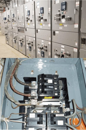
- Main Switchgear/Main Distribution Panel Board
- Main protective device
- Branch protective devices
- Generator circuit breakers
- Busways
- Motor Control Centers (MCC’s)
- Transformers (external thermal patterns)
- Downstream panel boards including protective devices
- Transfer switches
- Certain equipment disconnect switches
- Control panels
- UPS systems
- Conductor connections within all this equipment
Since this equipment is essential to providing electrical power to the facility, we typically would include the listed equipment and shoot images of the potential hot spots.
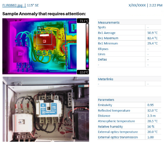
While on site, our team of certified thermographers remove the equipment covers to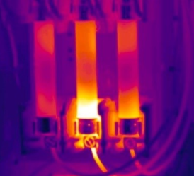 take the images (which are objective) to understand the temperature severity ratings (i.e. identify temperature differences and thermal anomalies).
Reference temperatures are compared to industry standards and guidelines to produce an objective temperature severity rating. We do this to inspect equipment for potential problems that can be identified before failing and causing unscheduled outages.
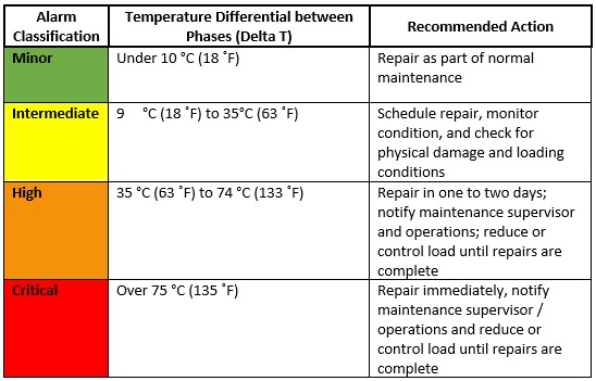
Temperature Differential Alarm Levels for Electrical Components
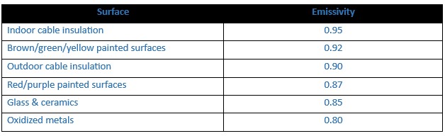
Emissivity
We determine the proper emissivity rating which is the ability of a surface to radiate energy that the camera can detect as compared to a perfect radiator (blackbody). Emissivity indicates the efficiency of radiation for a surface. Some sample emissivity ratings:
We then develop a report to document temperature differential levels for balanced electrical systems for acceptable operating temperatures, temperature differentials, and recommended actions when appropriate. We record the results for each anomaly and capture the following information when attainable:
- ID No. of equipment
- Temperature difference between area of concern and reference area
- Probable cause of temperature difference
- Load conditions (if able to do so)
- Save photograph (digital)/thermogram and archive for historical review (data trending)
We use the following for our inspection list:
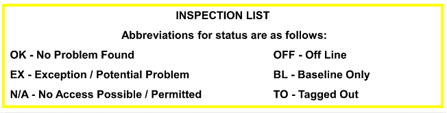
Note: A spreadsheet is also provided that includes a list of all equipment imaged/location for reference and will identify the alarm levels as listed in the alarm levels above.
Requires Immediate Attention

Thermography and Associated Challenges:
An IR Thermography study can provide valuable information, but it needs to be done properly. NFPA 70B states:
“IR inspections should be performed by qualified and trained personnel who have an understanding of infrared technology, electrical component maintenance…”
There are several important aspects to receiving accurate data that can present challenges in the field:
- Untrained operator – inexperience could report on false “hot spots”
- Accuracy of temperature
- Load is very important – is the equipment loaded at the time of the image
- Heating with low load is very serious
- Time of use or cycle
- Heat transfer effects – wind, ambient or environment conditions. Determining the right temperature
- Direct vs. Indirect images (covers open or closed)
- Ex: Transformers are dangerous to open, therefore, indirect image is utilized and temperature consideration needs to be understood)
- Entering correct object parameters in the camera. Emissivity is the single most critical attribute for accurate thermal measurement
- Reflection
- Glass (avoid glass) – glass could appear uniform in temperature but appear otherwise due to influence of other light, the sun, clouds, sky
- Shiny busbar
- Focus, Range and Distance (FORD) – very important!
- Thermogram must be in focus
- Correct temperature range and span
- Span is the portion of the range that you are viewing at a given moment
- Use of appropriate working distance to target
- Hot spot optically resolved – be careful with the zoom function. Zoom function only enlarges pixels; does not provide optical enhancement

Essentially, this is a brief overview of the electrical equipment we typically inspect with IR Thermography and some of the challenges we face. The important thing to remember; it is a “Science” and it’s not just about using an IR camera. The user must understand the many parameters involved around the concept, the environment, equipment conditions, reflectivity and so on. Remember the “FORD” rule!
This concludes Blog 3 “Electrical Applications and the Challenges”.
I hope the information was useful. In my next Blog and final blog for this series, we will discuss “The Benefits Combining Infrared Thermography with an Arc Flash Study.”
About the Author:
Scott has retired from Hallam-ICS, but his contributions to the company continue to be valued.
About Hallam-ICS:
Hallam-ICS is an engineering and automation company that designs MEP systems for facilities and plants, engineers control and automation solutions, and ensures safety and regulatory compliance through arc flash studies, commissioning, and validation. Our offices are located in Massachusetts, Connecticut, New York, Vermont and North Carolina and our projects take us world-wide.


What Is an Arc Flash Study? NFPA 70E Requirements Explained
The Benefits of Infrared Thermography
Comments (1)