
by Elizabeth Engler on Dec 11, 2025 10:30:01 AM
Introduction
When measuring and monitoring plant utilities, accuracy and reliability are everything. In this project, we needed to measure both hot water and compressed air flow in outdoor, industrial environments without disrupting operations.
To meet those requirements, we selected Emerson’s Flexim Fluxus Ultrasonic Flow Meters, which combine non-invasive installation, robust accuracy, and easy data integration. This blog takes a deeper look at the installation process, system performance, and how we connected these meters to Ignition dashboards for real-time monitoring.
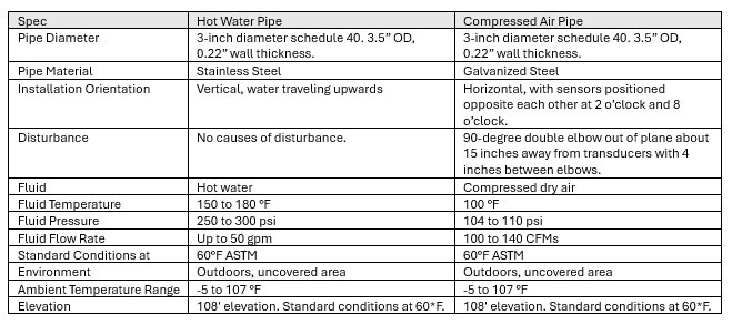
Understanding the Flow Application and Conditions
Our sensor choice had to meet the requirements of the pipe, fluid and environment, as well as provide highly accurate data that would allow us to track total fluid usage over time.
Why We Chose Emerson Flexim Fluxus Flow Meters
We selected Emerson for their proven reliability, build quality, and excellent support. The Flexim Fluxus line stood out for its non-invasive design and ease of installation, perfect for retrofit projects or sites that can’t afford downtime.
Key Advantages of the Flexim Fluxus Line
- Non-contact, non-invasive: No pipe cutting, drilling, pressure loss, or contamination risk. Safe for sanitary and food applications. There’s no risk of material buildup affecting the measurements.
- Handles low flows: Maintains accuracy down to flows of 0.01 m/s or 0.03 ft/s with no zero drift, thanks to factory calibration and signal processing.
- Easy Installation: Bidirectional and self-correcting transducers with flexible mounting arrangements.
- Superior ultrasonic measurements: Due to careful matching of piezoelectric elements, which produce stronger, cleaner signals, and noise suppression. Performs well even with thick pipe walls or other challenging conditions.
- Durability: Stainless-steel housings and ceramic components to withstand harsh environments and vibration.
- No field calibration or recalibration: Sensors come factory-matched and pre-calibrated.
Advanced Measurement Modes
TransitTime: The default mode of measurement using the transit-time principle.
NoiseTrek: For fluid with high gas bubbles or solids.
HybridTrek: Auto-switches between TransitTime and NoiseTrek for mixed conditions.
FastFood: High-speed measurement to handle highly dynamic flows. Disables continuous adaptation in favor of faster processing.
- Wealth of information: Available over a variety of communication protocols:
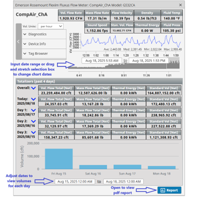
- Real-time Volumetric and Mass Flow Rates, Positive and Negative Flow Rates, Flow Velocity, Fluid Density, Fluid Temperature, Sound Speed, Standard Volumetric Flow (compressed air only), Thermal Energy, Fluid Pressure.
- Daily Total Usage (Totalizers) for past 4 days (including today).
- Overall Total Usage since last reset.
- Real-time diagnostic values: Signal-to-Noise Ratio (SNR), Signal to Correlated Noise Ratio (SCNR), VariAmp (turbulence indicator), VariTime (transit-time consistency), Signal Amplitude, Quality, Amplification, Transducer Temperature, Correlation Coefficient, Crest Factor, Peak Width, Symmetry of Amp, Signal Symmetry, and Sensor Humidity.
- Device Info: IP address, Modbus addressing type, Error Delay, Firmware version, Heartbeat, Response Delay, and Start Time.
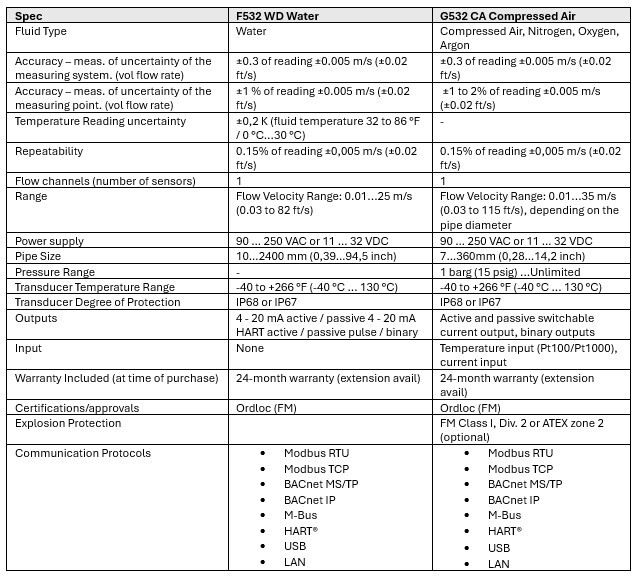
Together, these features made the F532 WD Stationary Ultrasonic Water Flow Meter and G532 CA Compact Compressed Air Flow Meter ideal for our applications.
Product Specifications:
Technology and Hardware:
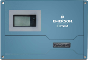
Figure 1 Flexim Fluxus Transmitter Exterior with door cover in place.
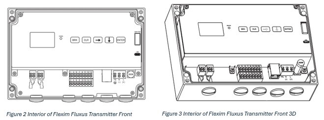
The Flexim Fluxus Transmitter processes the signals and data received from the ultrasonic transducers mounted on the pipe. The display and buttons are used to view status, settings, configuration and parameter menus, and diagnostic data. The transmitter can be mounted in a variety of ways including on a wall, panel, pipe, pole, or frame. It is completely sealed from the elements when the door is affixed and offers IP66 protection and a temperature rating of -4 to 140 °F (-20 to 60 °C). Connecting to the transmitter over the network or by USB-C allows you to use their Flexim FluxDiag software on a PC to view and download more detailed historical trend data for each flow measurement, edit configuration settings, and check diagnostics.
How Ultrasonic Flow Measurement Works
Transit-time difference principle
Emerson Flexim Fluxus flow meters use the transit-time difference principle to measure flow velocity in liquids or gases. Each transducer contains a piezoelectric element, which generates ultrasonic waves (typically in the range of 0.2-2 MHz) through vibrations when an electrical voltage is applied. The first transducer emits an ultrasonic signal which travels at an angle through the pipe wall, is slowed or sped up by the fluid flow, and is received by the second transducer. Depending on the separation of transducers and reflection versus diagonal arrangement, the signal may bounce off the pipe wall a few times. The signal received by the second transducer causes its element to vibrate, converting the mechanical energy back into an electrical signal. These transducers alternate roles on each cycle (e.g. Transducer A sends to B, then B sends to A), which allows the meter to capture transit times in both directions.
Precision Through Acoustic Matching
Emerson transducers set themselves apart from the competition by using high-quality piezoelectric ceramics and a unique selection process. They carefully pair transducers in the factory for “perfect acoustic matching”, which ensures identical piezo characteristics, reducing errors from mismatches. Competitors may use off-the-shelf pairs, leading to drift and more calibration time. The pairing process along with advanced calibration results in zero-point stability (no zero drift over time) and high accuracy (±0.5–1% typical, even at low flows).
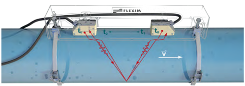
Figure 4 Diagram demonstrating ultrasonic measurement.
Reliable Support and Service
Our sensors for water did not require much adjustment, but the compressed air sensors required a little tinkering with transducer distance and sound paths, for which Emerson’s local support staff were very helpful. We communicated over email, phone, and they even offered to travel out for a visit and assist in person, which wasn’t necessary. When we seemed to be short on coupling pads for the sensors, they sent us a complimentary pair and quoted refills on the coupling lubricant. They shared installation tips specific to our application, troubleshooting, guidance on installation procedures, picture guidance, manual references, and were always quick to respond with useful information.
Installation Guide
Installation Tips
Whether measuring water or air, proper installation ensures accurate, reliable data.
Here are the best practices we followed:
- On Horizontal Pipes: Mount laterally (on the sides) to avoid gas bubbles (on top) or sediment (on bottom) interfering.
- On Vertical Pipes: Ideal if liquids flow upwards to ensure the pipe is full and avoid splashing or uneven flow.
- Avoid disturbances like elbows, valves and junctions (keep 10–20 pipe diameters away upstream – the manual defines specifics per scenario).
- Use permanent coupling pads/foil (not gel, which degrades) for acoustic contact, acoustic couplant/lubricant (silicone based, high temperature for outdoors and hot areas/pipes), and stainless-steel straps to mount securely.
- Don’t forget to use plenty of acoustic couplant (lubricant) between the transducers, couplant pads, and the pipe. For compressed air, wrap the adhesive damping mats around the pipe to prevent noise before installing the transducers on top. See pictures below for more detail on how these are installed.
- Start transducers close together with fewer sound paths to start and adjust outward or inward with more sound paths to get a stronger or more accurate signal. Refer to the installation manual and recommendations provided by the transmitter on the setup menu.
We experienced Emerson’s excellent local and remote support resources. If any questions or challenges come up, they are quick and willing to lend a hand, offer in-person assistance, communicate remotely over the phone and email, discuss scenarios, and troubleshoot problems.
Installation of Flexim Fluxus F532 WD for Hot Water
For liquid applications with vertical flow, it is best if the flow is upwards. The transducers are mounted within rails and can be in a reflection or diagonal arrangement. For this application a simple reflection arrangement with a double beam was sufficient. Installation is permanent, simple, and non-invasive since there is no pipe cutting or drilling and no stop to operations and flow. The materials are robust against the outdoor elements and there are no moving parts so we should never have to worry about repairs or replacements. Once it’s in place and configured, we never give it a second thought and just enjoy receiving rich and detailed data.
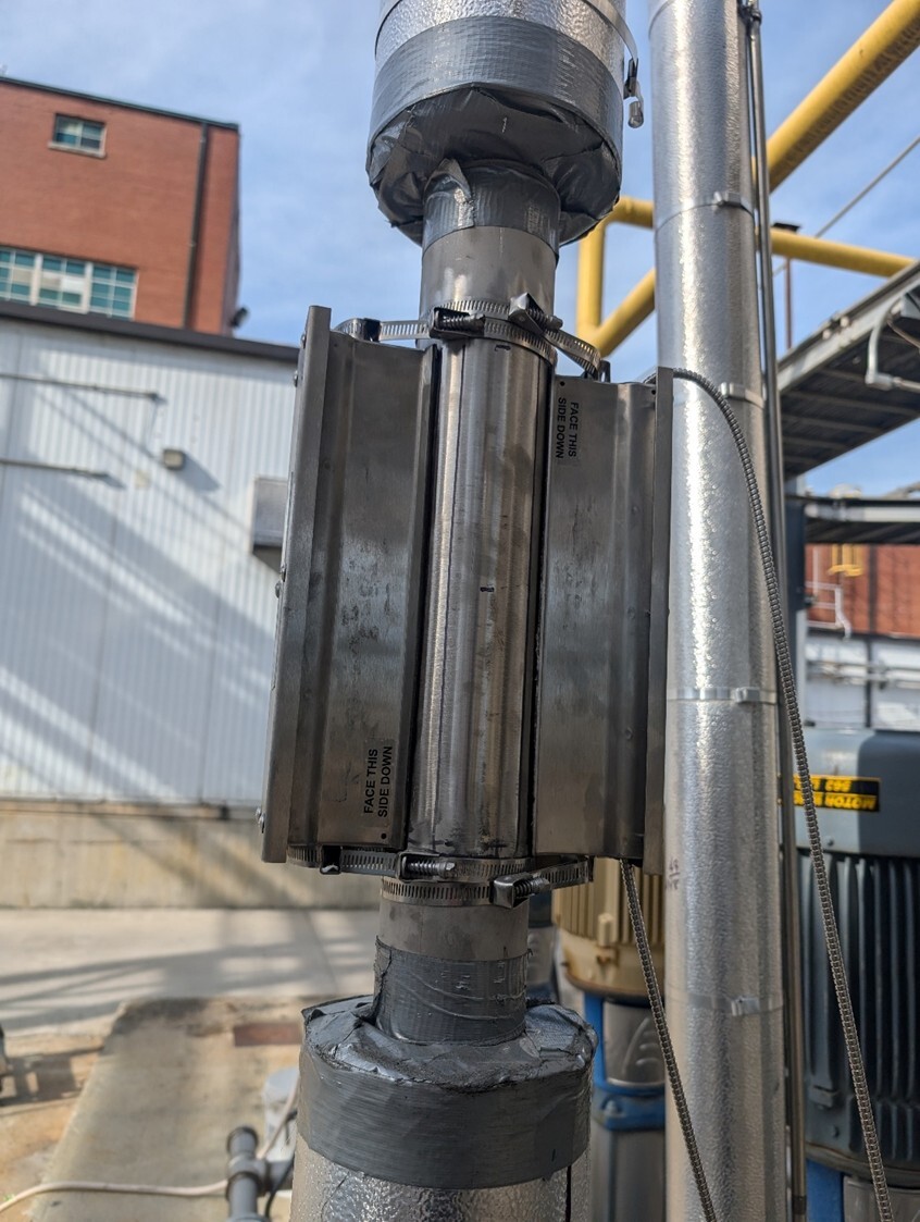
Figure 5 Hot Water Pipe with F532 WD ultrasonic flow meter installed. Water flows upwards. Transducers are installed in one rail in a double-beam reflection arrangement. The F532 WD transducers use coupling pads (more pictures shown below), but do not require damping pads on the pipe
Installation of the Flexim Fluxus G532 CA for Compressed Air
The compressed air pipe is made of galvanized steel with a “T” joint and elbow at one end. The pipe material as well as the cause of disturbance can make measurements a little trickier and this installation required a little more tinkering to achieve the right arrangement.
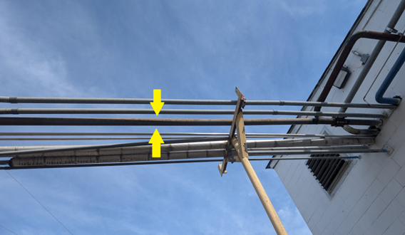
Figure 6 Compressed Air galvanized steel pipe.
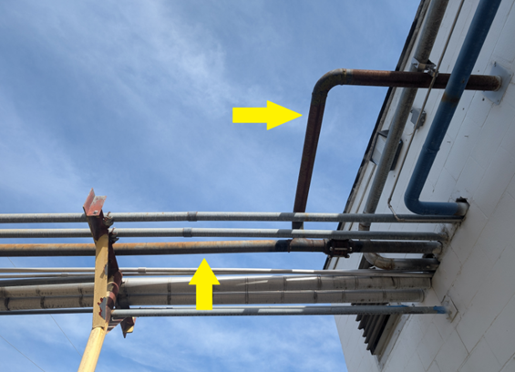
Figure 7 Compressed Air galvanized steel pipe. "T" and right-angle joints are causes of disturbance.
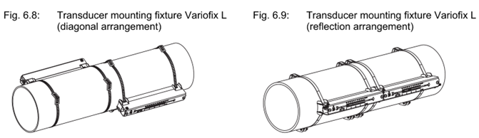
Figure 8 Mounting diagram of rail fixtures from G532 CA and F532 WD installation manuals.
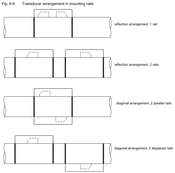
Figure 9 Mounting diagram of transducers within mounting rails from G532 CA and F532 WD installation manuals.
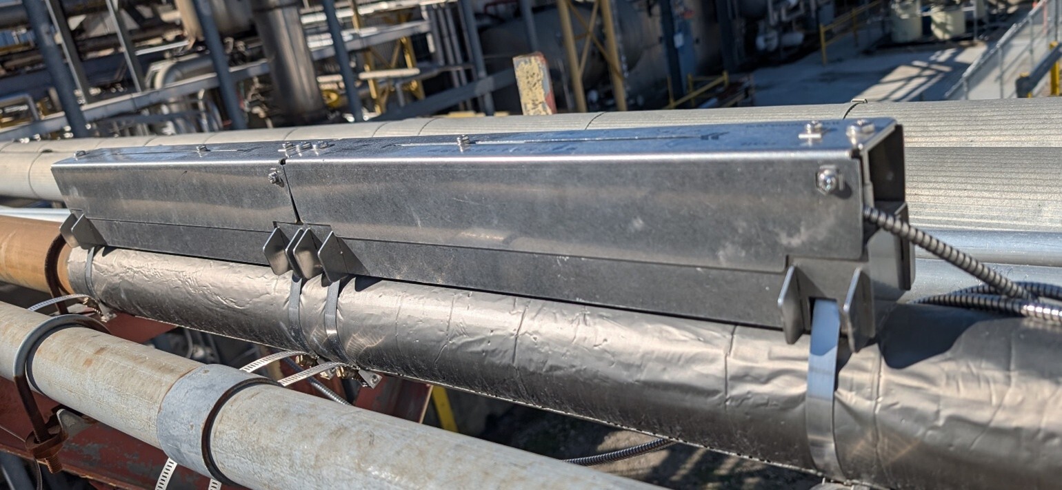
Figure 10 Initially we tried the reflection arrangement with 2 rails, but found diagonal arrangement worked better for our application.
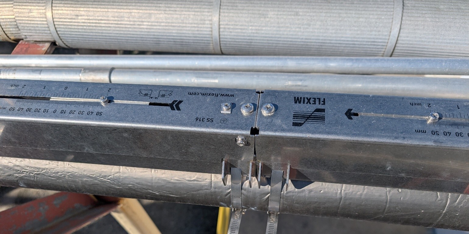
Figure 11 In any arrangement, arrows must be pointing in the same direction. Transducers slide and are screwed in place inside the Variofix mounting fixtures (rails).
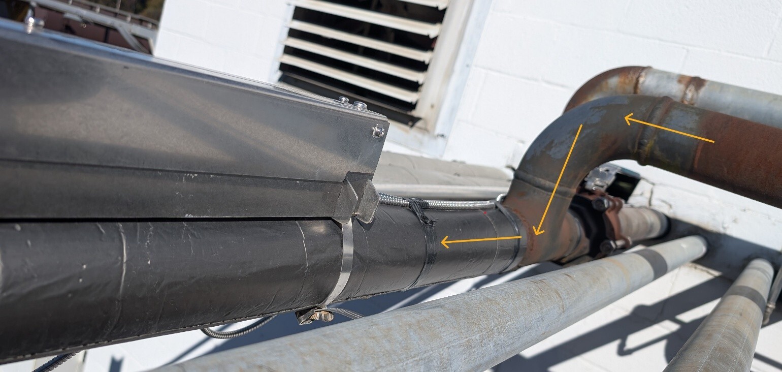
Figure 14 For compressed air, adhesive damping mats are wrapped around the pipe to reduce the propagation of acoustic noise in the pipe wall, especially if it is not possible to keep the recommended distance to the reflection points. The yellow arrows indicate the double elbow out of plane, a cause of disturbance, and the direction of air flow. Ideally, the sensors should be installed at least 40x the pipe diameter away from a double elbow disturbance, however this area was easiest to reach by ladder for the plant maintenance personnel. The G532CA’s advanced signal processing and damping mats have ensured reliable measurement despite the nearby disturbance, demonstrating its robustness in challenging setups.
Acoustic couplant is used for both liquid and air applications, spread on both sides of the coupling pad placed between a transducer and the pipe. Friction and the lubricant hold the pad in place on the transducer. For compressed air applications it is recommended to use the provided adhesive damping mat material wrapped around the pipe according to the recommendation for your specific application.
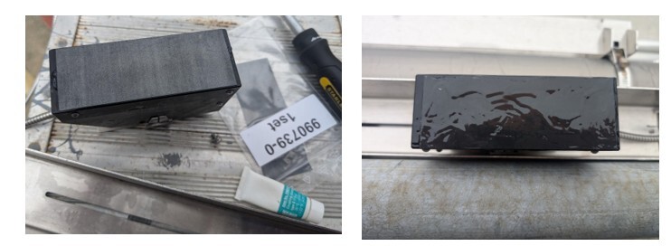
Figure 13 (left) Transducer bottom with coupling pad applied using acoustic couplant (silicone based, high temperature) for ultrasonic flow meters between the pad and transducer. (before applying more couplant on the outside). Figure 13 (right) Transducer bottom with coupling pad applied using acoustic couplant (silicon based, high temperature) between the pad and transducer, as well as coating the outside of the pad with more couplant (on both sides).
Initially, we tried a reflection setup but achieved stronger, more stable readings with a diagonal configuration using rails mounted in parallel and angled on the pipe to keep the beams more lateral, rather than up and down. We also wrapped adhesive damping mats around the pipe to reduce acoustic interference and applied generous acoustic couplant for best signal quality. Even with less-than-ideal proximity to pipe disturbances, the G532 CA’s signal processing algorithms maintained excellent reliability.

Figure 15 Final Installation of the G532 CA laterally mounted, diagonal arrangement, with 2 parallel rails. Angled on pipe to fit between nearby pipes and measure as laterally as possible.
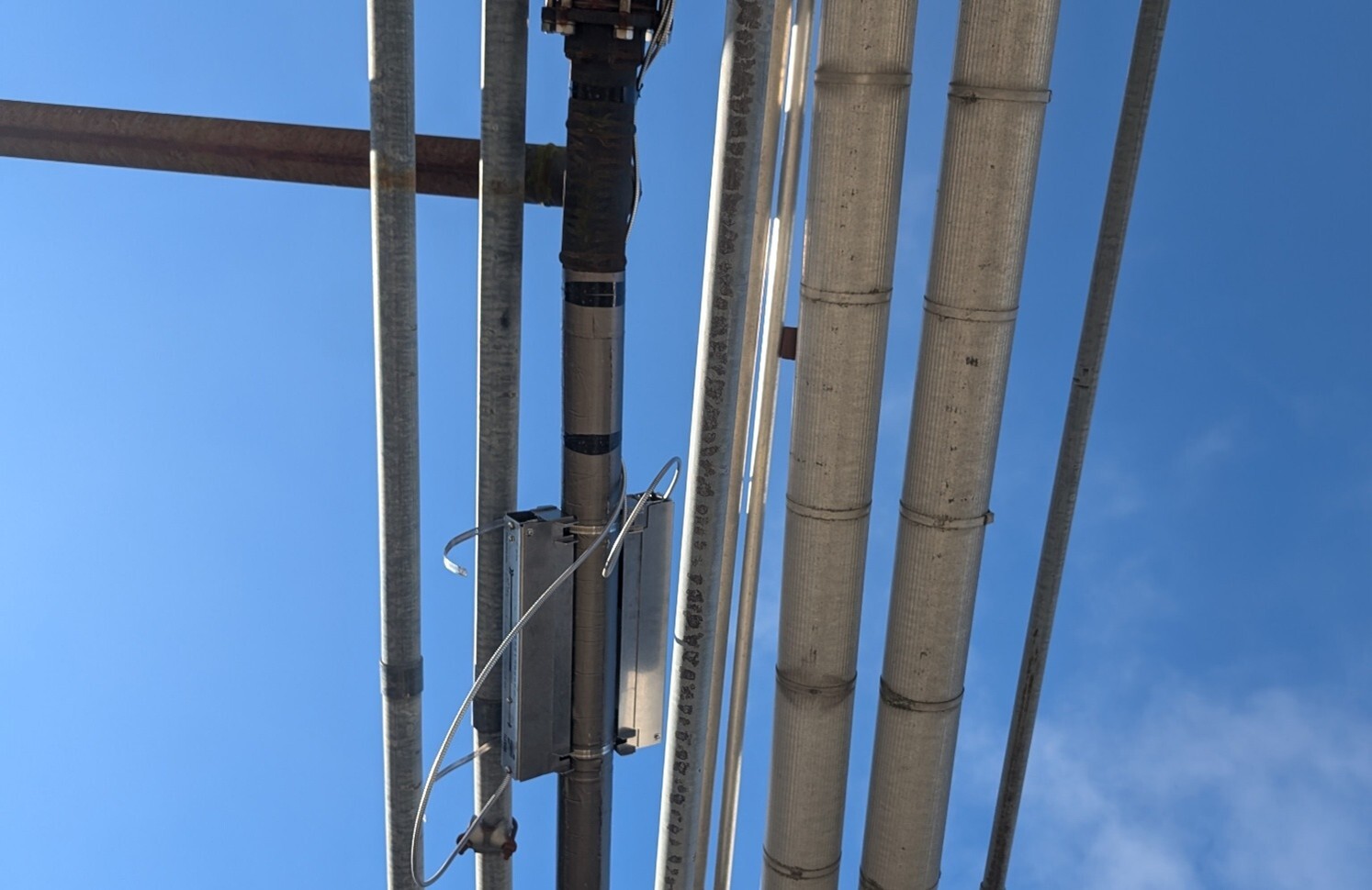
Figure 16 Final Installation of the G532 CA laterally mounted, diagonal arrangement, with 2 parallel rails. Angled on pipe to fit between nearby pipes and measure as laterally as possible.

Figure 17 Final Installation of the G532 CA laterally mounted, diagonal arrangement, with 2 parallel rails. Angled on pipe to fit between nearby pipes and measure as laterally as possible.
Common Installation Challenges and Solutions
|
Challenge |
Solution |
|
Limited space near disturbances |
Use diagonal and lateral mounting, damping mats, and always use acoustic couplant (hi-temp silicone lubricant). |
|
Turbulence, bubbles, solids |
Use NoiseTrek mode if severe, HybridTrek mode if minimal. Mount transducers laterally (on sides of pipe). |
|
Uneven signal readings |
Adjust transducer spacing and sound paths count incrementally. |
|
Outdoor exposure |
Flexim Fluxus housings, transducers and parts are made to withstand harsh weather outdoors. |
These lessons reinforced why ultrasonic meters are ideal for non-intrusive, harsh-environment monitoring.
Remote Visualization with Ignition Dashboards and Trends
Integrating with Ignition Dashboards
Ignition is a platform for SCADA, MES, IIoT and custom application development. It empowers each department of this manufacturing plant to track operations, efficiency, yields, and plan for upcoming production. Once installed, we connected both meters to Ignition using the Modbus TCP driver to visualize data and track long-term trends.
Real-Time Dashboards and Historical Trends
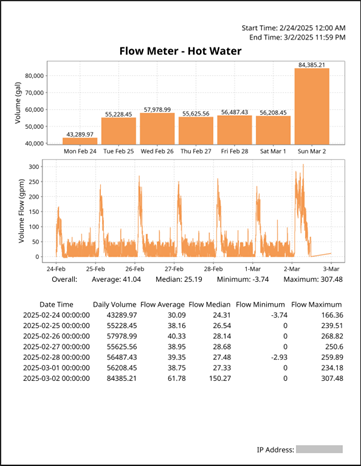
We built custom dashboards to display real-time values, totalizers, and historical trends. Using Ignition’s Tag Historian, we logged key parameters such as flow rate, pressure, and temperature. Real-time dashboards give operators clear insight into daily usage, while automatic reports summarize weekly trends and highlight anomalies.
Data Points Summary
- Flow velocity, mass flow, and thermal energy
- Fluid temperature and density
- Diagnostic metrics such as SNR, VariAmp, and correlation coefficients
- Daily and cumulative totalizers
This integration provides a single view of system performance, empowering teams to identify inefficiencies and optimize resource use.
Key Takeaways
- Fast, non-invasive installation with zero downtime.
- Reliable data in challenging environments.
- No recalibration needed for years of service.
- Seamless integration with Ignition for visualization and reporting.
Frequently Asked Questions (FAQ)
What makes ultrasonic flow meters better than mechanical ones?
They’re non-invasive, offer easy and fast installation, and require little to no maintenance. This makes them ideal for applications where uptime and cleanliness matter.
Can ultrasonic flow meters measure compressed air?
Yes. Emerson’s G532 CA model is designed specifically for gases like compressed air, nitrogen, and oxygen, maintaining accuracy even near pipe disturbances.
How can I view flow data in real time?
By integrating Emerson meters with Ignition dashboards, you can view live data, analyze historical trends, and receive automated reports directly from your system.
Ready to improve visibility into your plant’s utilities and flow systems?
Contact Hallam-ICS to discuss instrumentation and data integration solutions for your facility.
About the author
Elizabeth Engler is a Controls Integrator with diverse experience across controls design, programming, and software development. She enjoys logical challenges, user interface design, and programming machines to bring customer's visions to life. In her free time, Elizabeth enjoys gardening, mysteries, movies, and time with family.
Read My Hallam Story
About Hallam-ICS
Hallam-ICS is an engineering and automation company that designs MEP systems for facilities and plants, engineers control and automation solutions, and ensures safety and regulatory compliance through arc flash studies, commissioning, and validation. Our offices are located in Massachusetts, Connecticut, New York, Vermont, North Carolina and Texas and our projects take us world-wide.
How Emerson Flow Meters and Ignition Dashboards Drive Efficiency
Linking Emerson Level Sensors to Ignition Dashboards for Real-Time Tank Insights

No Comments Yet
Let us know what you think