
by Elizabeth Engler on Jan 22, 2026 10:30:01 AM

Follow along as we share with you our steps to set up this solution, the reasoning behind our choice of guided wave radar, and the settings that gave us reliable liquid level data across multiple layers underneath a thick crust.
When a waste tank develops a thick crust above the liquid level with an air gap in between, non‑contact radar can miss or misread the true level. We implemented an Emerson Rosemount 5301 guided wave radar with Modbus and Ignition SCADA to get reliable level data, enforce dump scheduling, and reduce disposal cost.
The Situation
Our application presented unique challenges since we are measuring waste brine product from a meat injection process. The substance is a mixture of water, fats, sugars, chemicals and salt. As it sits, fats rise to the top, solidify and form a thick crust which sticks to the sides of the tank.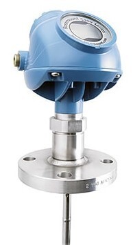
Over the course of being drained and refilled with waste, the liquid level drops below the crust and there is a gap of air in between the bottom liquid and the top crust. A non-contact radar sensor would not work since the signal would just bounce off the ever-present top crust. We needed a sensor that could distinguish between the different layers and give us the level of liquid below the crust.
Decision: move to guided wave radar (Emerson Rosemount 5301) so the measurement follows a probe down to the real liquid surface.
Why Non‑Contact Radar Was Not Suitable
- Process reality: Thick, sticky crust forms on top of the liquid; liquid level changes, but the crust remains, creating an air gap between and hiding the actual liquid level.
- Measurement effect: Conventional non‑contact radar reflects off the crust/foam, not the actual liquid surface.
- Why guided wave: A probe-guided impulse travels down to the actual liquid interface, delivering stable readings even with buildup or vapor.
- Model note: 5300 family overview — 5301 (level), 5302 (interface), 5303 (solids).
Guided Wave Radar 101 (Rosemount 5300 Series)
The guided probe style sensor excels at detecting varying levels of layered material in a tank and can calculate each layer’s level, interface (boundary between unmixing materials), or ullage (empty space between levels).
The transmitter guides low power, nano-second microwave pulses down a probe immersed in the process medium. At each change of the dielectric constant (or change in material) a portion of the pulse’s energy is reflected and the residual wave continues down the probe.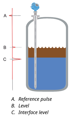
The transmitter uses the Time Domain Reflectometry (TDR) principle, or time-of-flight measurement, and converts the time difference between each sent and reflected pulse to a distance.
Capabilities making this the right tool for the job:
- Handles vapors, foam, buildup, turbulence, boiling, and changes across pH, viscosity, density, temperature, and pressure unlike non‑contact
- High accuracy/resolution for small changes that drive scheduling and inventory.
- Diagnostics (signal strength/quality) help validate reliability.
- Probe options (rigid rod/flexible cable) to match tank geometry and media.
Result: Fewer false readings, dependable trends, and confident operations decisions.
Key Benefits of Rosemount 5300 Guided Wave Radar
- Accurate and reliable level measurement for liquids, solids, layers and liquid interfaces
- No moving parts, no re-calibration, minimized maintenance
- Handles vapor, dust, slurries, turbulence, foam and changes in density, conductivity, viscosity, pH, temperature and pressure well
- Unaffected by small tanks, difficult tank geometry, internal obstacles, or mechanical design
- Advanced signal processing algorithm can distinguish between liquids with a top layer down to 1 in. (2.5 cm)
- Dynamic Vapor Compensation assures accuracy even in saturated steam
- Direct Switch Technology improves efficiency of signals resulting in 2-5x stronger reflections for increased sensitivity, and better detection of low-dielectric or viscous media
- Probe End Projection filters out noise from the probe end, boosting accuracy
- Smart Galvanic Interface proprietary hardware design isolates device electronics from the probe assembly for optimal performance and stability. Especially helpful for industries such as oil & gas, chemicals, and pharmaceuticals.
- Third party approved for overfill prevention and Safety Integrated System SIL3 suitability
- Rigid probe provided for our application composed of 316/316L stainless steel which includes molybdenum for improved corrosion resistance and performs well in seawater, food processing, chemicals, and chloride-containing solutions. Wide range of probe styles, and materials for various material, temperature, and pressure requirements.
- Data output options include 4-20mA HART®, FOUNDATION™ Fieldbus, Modbus®, or IEC 62591 (WirelessHART®).
- Easy set up with user-friendly software, echo curve and logging tools.
Configuration Overview for Modbus Communication
Goal: Get level, volume, and health diagnostics out of the transmitter via Modbus (HART is also available).
Summary:
- Initial device setup (HART/AMS or local interface)
- Verify device tag, units, span, damping, and probe type.
- Confirm level/volume scaling and any needed offsets.
- Select Modbus variables
- Level (primary), Volume (if configured), Signal Strength/Quality, and Heartbeat/Status.
- Document the exact register map provided by Emerson for your build.
Pro tip: Save a baseline config once the probe is tuned. It’s your fast rollback if a future edit goes sideways.
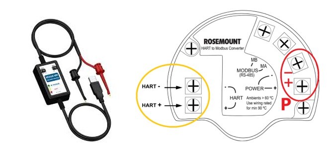
If you plan to collect data via Modbus, a portable HART modem and connector are required for the initial transmitter configuration. Since an Emerson technician handled this process for us, they brought their own modem and connector and saved us the effort.
Steps
- Disconnect power from the right power terminals of the device (circled in red in the figure below).
- Connect to the HART terminals (circled in yellow in the figure below), using the HART modem connector and a laptop. The HART modem will supply power with the correct resistance to the device. If you connect while still using external power, you will need a resistor between 250-1200ohms. Put one resistor end on the HART terminal, and twist the positive wire to the other end, then connect the modem leads across the resistor.

- Complete configuration data such as Tank Height, Upper Null Zone, dielectric constants, units, and other basic parameters using AMS Device Configurator and Rosemount Radar Master (RRM) from Emerson. After completing setup, verify the live measurement values match the actual current tank level measurement.
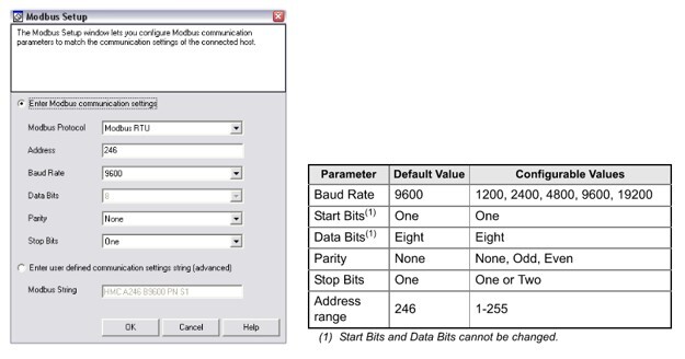
- Complete Modbus Setup and Assignment of variables using Rosemount Radar Master (RRM). Modbus communication must be enabled in settings. Refer to Rosemount 5300/5400 Series with HART to Modbus Converter Manual Supplement (Document No. 00809-0500-4530) starting at page “1-25” to “1-30”. These are the settings we used:
- Select which 4 variables to provide over Modbus (only 4 can be selected at a time). These are the variables and availability by model. We selected Level, Volume, Heartbeat, and Signal Strength:

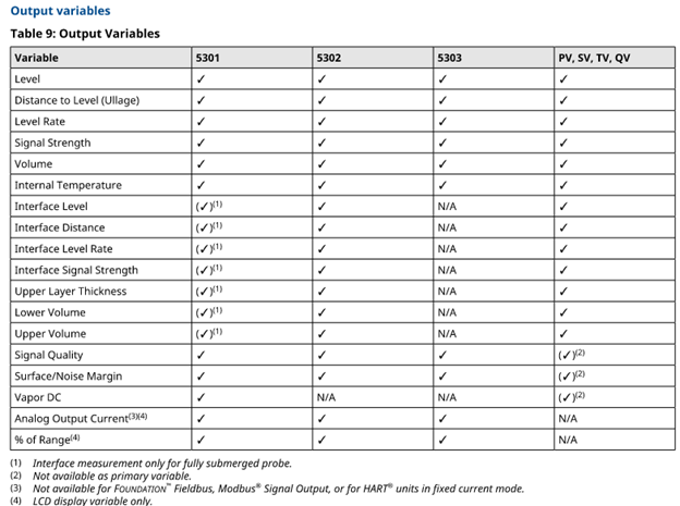
For more information, see the Rosemount 5300 Series Quick Installation Guide (Document No. 00825-0100-4530), Rosemount 5300 Series Reference Manual (Document No. 00809-0100-4530), and Rosemount 5300/5400 Series with HART to Modbus Converter Manual Supplement (Document No. 00809-0500-4530).
Setup for Data Collection using Modbus TCP
Convert from RS485 to Ethernet for Modbus TCP
The MA and MB terminals on the transmitter provide Modbus RTU communication over RS485. We planned to collect data over our plant ethernet network using Modbus TCP, so we used a simple RS485-to-ETH converter located in a panel beside the tank to convert the signal and connect to the plant network.
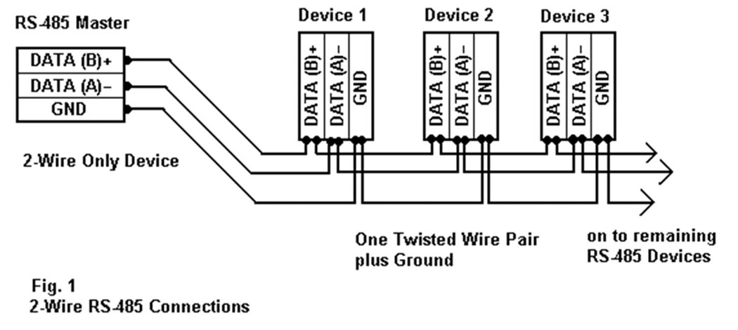
Wiring of Converter
- Connect the RS485-to-ETH converter DATA (A)- terminal (labeled 485A on ours) to the MA terminal on the transmitter.
- Connect the RS485-to-ETH converter DATA (B)- terminal (labeled 485B on ours) to the MB terminal on the transmitter.
- Supply 24VDC power from a power supply to the V+/V- terminals of the converter, and connect an ethernet cable to your network.
We used an RS485-to-Ethernet Converter from Waveshare, which was easy to set up and has been reliable, but there are many similar converters available.

Setup of Waveshare RS485 to ETH Converter
- Go to Waveshare’s Wiki guide for RS485 to ETH (B).
- Download the VirCom Software, then open it (run with .exe file, stored in RS485 to ETH Converter folder and zip file).
- Connect to the device over ethernet. Detect device with VirCom to view current settings and IP address. Follow instructions on the Wiki page for setup of IP address, mode, communication settings, and Modbus port using VirCom software.
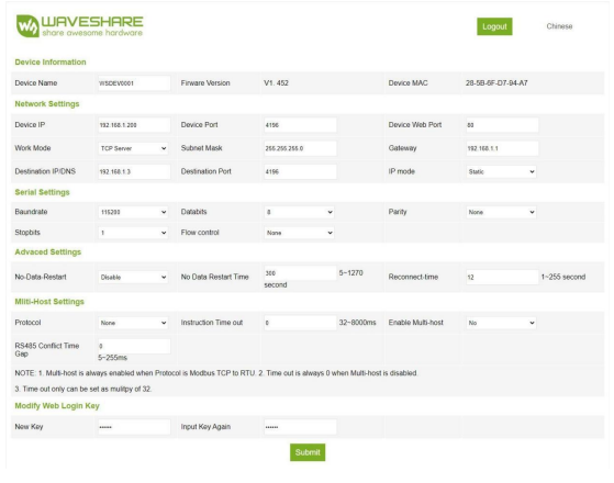
- Setup of communication settings can also be accomplished through Web Configuration in your browser, which I found to be most convenient. The first time you connect, open a web browser, and input one of these IP addresses in the url search bar: 192.168.1.254 or 192.168.1.200. Make sure your local network settings on your PC match the first 3 numbers of this IP address (go to Control Panel > Network Settings > Adapter > Properties > Iv4 settings, set to use Static IP, set the ip address to 192.168.1.xxx where “xxx” is any number between 2-199, accept the provided subnet address and leave gateway blank).
- Once the webpage loads, connected to your converter, enter a password in “Password:” - there is no login password set by default in the factory, you can enter a password at will, and click the Login button to log in. After setting the password to log in, the settings at "Modify webpage login password" will take effect:

- Modify desired parameters:
- Set Device IP to a unique static IP address which is reserved for this connection and not already used by any other device on your network. This IP address will be used to access data from the transmitter. And set subnet and gateway address to match those defined for your network. (Gateway address is usually the same first 3 numbers as your static IP, with “.1” at the end).
- Set Device Port to 502 (for comms between converter and RTU device).
- Set Destination IP same as the Device IP. Leave Destination Port default.
- Advanced Settings: Enable No-Data-Restart. If no data or comms are detected for a time, converter device will restart and try to re-establish communications.
- Protocol: Modbus TCP to RTU – so the converter can communicate with the RTU device (TCP to RTU), and the RTU device can communicate back (RTU to TCP).
- Click submit, and restart.

Test and View Modbus Data Values Using Modbus Poll
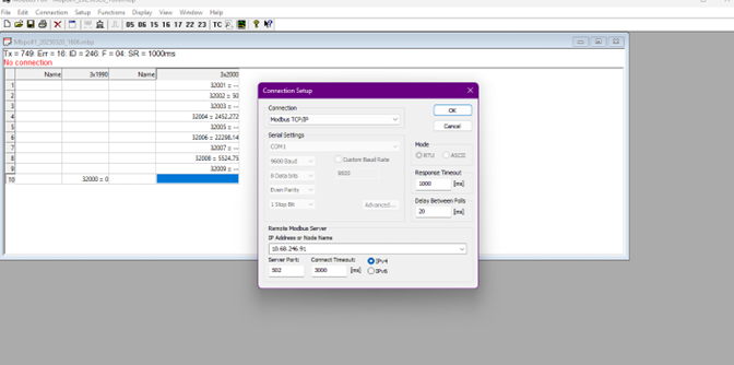
- Download, Install and Open Modbus Poll. Open the “Connection” menu item. Set Connection to “Modbus TCP/IP”, IP Address to the Device IP that you set on your converter, Server Port to 502, and select IPv4, then click “OK”.

- We found the best way to get good data was to look at Input registers 2000-2008 (Full addresses: 32000, 32002, 32004, 32006, 32008) using “Little Endian, Byte Swap” display. (See explanation of available registers and arrangements below).
Open “Setup” menu item and Read/Write Definition. Set parameters accordingly:
- Function: 04 Read Input Registers (3x)
- Address mode: Dec
- Address: 2000
- Quantity: 10
- Rows: 10
- Checkmark “Address in Cell” and “PLC Addresses (Base 1)”

- Open “Display” menu item, select 32-bit Float > Little-endian byte swap:
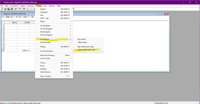
Now in the Modbus Poll window, you can view the raw data points being sent from the transmitter.
Explanation of Available Modbus Registers and Arrangements for the Emerson Transmitter
Format Codes determine the arrangement of bytes in the registers for interpreting the registers into readable data.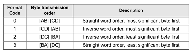
Each set of registers displays the data in a different arrangement matching one of the format codes.
Input Register Sets:
- Format Code 1: 1300-1308 for slave 1 data.
- Format Code 0: 2000-2008 for slave 1 data. ⬅️ We used this one.
- Format Code 2: 2100-2108 for slave 1 data.
- Format Code 3: 2200-2208 for slave 1 data.
- Each variable is a 32-bit Floating Point.
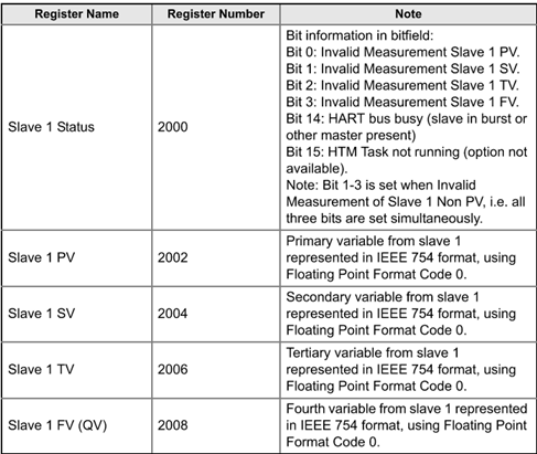
Register Set Order and Data Descriptions:
Ignition by Inductive Automation for Data Collection and Display
Our client utilizes Ignition by Inductive Automation extensively for unified data collection, monitoring, and custom application development across all their departments. The diversity and flexibility of available device drivers and communication protocols enable us to connect virtually any device, PLC, sensor or instrumentation over our plant network and collect valuable data. We use this data to provide actionable insights, trigger alarms, drive plant efficiency, compile regular shareable reports, and save for historical records and trends.
Setting up the Ignition device connection to our Emerson Rosemount Level transmitter using the Modbus TCP converter was a breeze. Emerson technical support provided quick responses to any questions about Modbus addressing as we set up tags in Ignition to view and collect the datapoints.
Device Connection in Ignition
First, add the device in the Ignition Gateway Configuration > OPC UA: Device Connections page: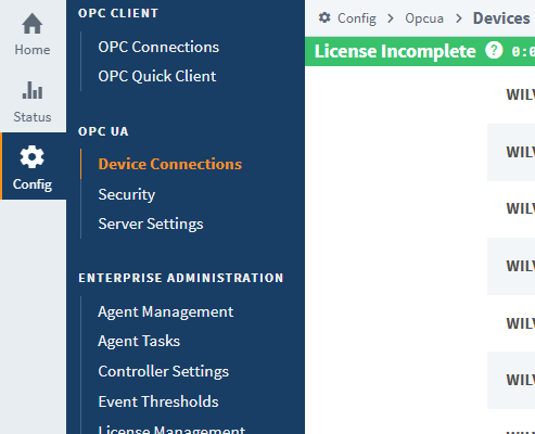
At the bottom of the page, select “Create New Device…”, and Select Modbus TCP.

Give the device a name, fill in the IP address (matching the Device IP set for your RS485-to-ETH converter) and port 502, select Show Advanced properties:
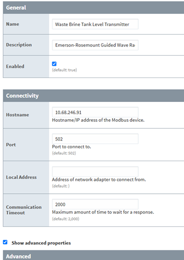
Under Advanced, checkmark “Reverse Word Order” and “Reverse String Byte Order” (not checked by default), then Save Changes (These are the settings to use if using “Format Code 0” defined in the transmitter’s modbus configuration, which is the default):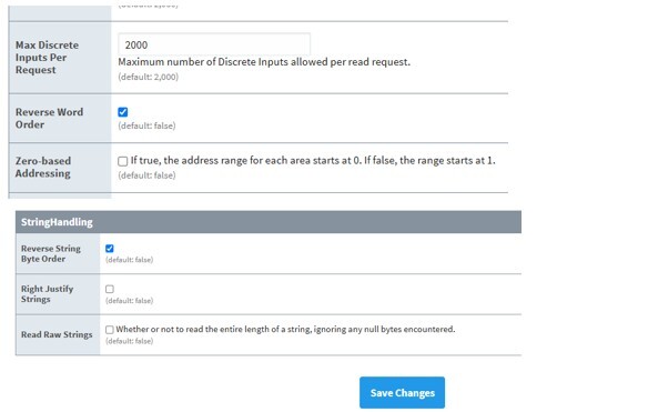
Tag Creation in Tag Browser of Ignition Designer and Modbus Addressing
In Ignition Designer, add tags to the tag browser using these settings:
- Value Source: OPC
- Data Type: Float
- OPC Server: Select the one named for your gateway. Usually something like “Ignition OPC-UA Server” or similar.
- OPC Item Path: “ns=1;s=[DEVICENAME]246.IRF2002”
- ^ The above OPC Item Path gets the value for Register number 2002, representing the Primary Variable from Slave 1 which you selected to receive in the transmitter Modbus configuration. (For our application, this gets the Level measurement).
Check the Ignition Manual documentation on Modbus Addressing to understand the formatting:
The OPC Item Path explanation:
- ns=1 : refers to namespace an OPC UA node belongs to. In this case all tags from devices are in index 1.
- [DEVICENAME] : In Ignition gateway configuration, go to OPC UA > Device Connections. Add your device and give it a name. This is the device name.
- 246 : Slave ID of the device. In this case it is 246.
- IRF2002 : “IR” is used for input registers. “F” is used for floating point values. “2002” is the register address for our primary variable (full address 32002).
Examples of our in-use tags settings:
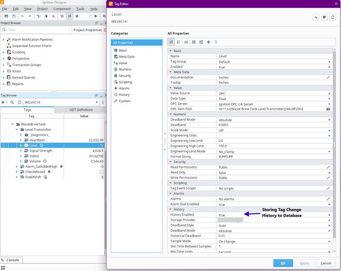
Figure 1: Level Measurement value with Tag History enabled.
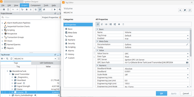
Figure 2: Volume value.
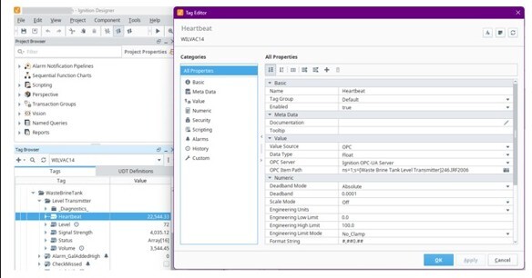
Figure 3 Heartbeat value.
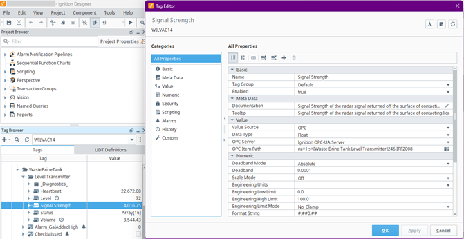
Figure 4 Signal Strength value.
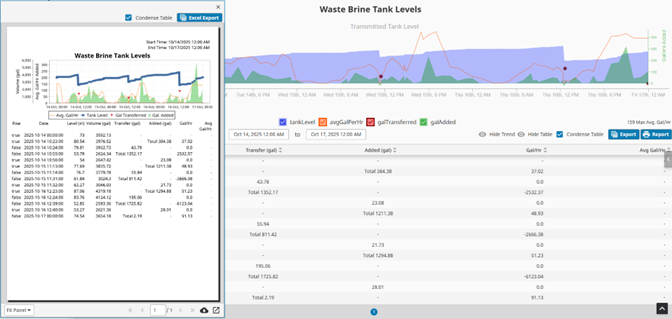
Ignition Dashboards and Reports for Actionable Insights
The purpose of obtaining these level measurements was to gain reliable visibility of tank fill and drainage cycles, identify high-fill-rate periods and potential misuse, and enforce a more efficient dump/drainage schedule to minimize the cost of disposal since this was for a waste collection tank. We used Ignition’s convenient drag-and-drop user interface to create an intuitive trend chart, table, and custom PDF report. We used custom scripting to organize, condense and filter all saved data to show users exactly what they want to see from the high-level overview to the granular individual changes in tank level.
Learn more about integration into Ignition and creation of dashboards and reports.
FAQ
Q1: When would you choose 5301 (level), 5302 (interface) or 5303 (solids)?
Choose 5302 when you must measure and track the interface (point of contact) between two immiscible liquids in the case of multiple layers; 5301 is for single‑phase level; and choose 5303 when measuring solids.
Q2: Why did we reverse word/string order in Ignition?
The 5300’s Modbus float mapping in our case uses “little-endian with byte swap” word order readable in Ignition with Reverse Word Order (and Reverse String Byte Order for strings).
Q3: Which input registers should I read first to test?
Start with Input 2000–2008 as 32‑bit floats; verify level and volume values are sane before building displays.
Q4: Can Hallam‑ICS help implement dashboards and reports?
Yes, our MI and controls teams deliver Ignition projects, KPIs, and OEE dashboards across industries.
Where Hallam‑ICS Can Help Next
- Process Control & Plant Automation: PLC/SCADA, panel fab, standards, and secure networking.
- Manufacturing Intelligence: KPIs, OEE, enterprise reporting, Ignition dashboards.
- Instrumentation & Calibration: Device selection, installation quality, loop checks, and PM strategy.
Call to Action: Schedule a consult to review your tank instrumentation and data strategy (Modbus/OPC, KPIs, reporting).
About the author
Elizabeth Engler is a Controls Integrator with diverse experience across controls design, programming, and software development. She enjoys logical challenges, user interface design, and programming machines to bring customer's visions to life. In her free time, Elizabeth enjoys gardening, mysteries, movies, and time with family.
Read My Hallam Story
About Hallam-ICS
Hallam-ICS is an engineering and automation company that designs MEP systems for facilities and plants, engineers control and automation solutions, and ensures safety and regulatory compliance through arc flash studies, commissioning, and validation. Our offices are located in Massachusetts, Connecticut, New York, Vermont and North Carolina, and Texas and our projects take us world-wide.

Top 5 Benefits of Process Control Systems in Manufacturing

Emerson Ultrasonic Flow Meters: Installation Guide and Data Insights

No Comments Yet
Let us know what you think