Flammable Gas Sensors-Wonder Out Loud
by John Kurowski on Jul 29, 2021 10:30:00 AM

Have you ever thought about your flammable gas monitoring? Have you really thought about how it works? If you have more than one flammable gas, did you ever wonder how one device can tell you percent of LEL for multiple gases knowing that each gas has a different 100% LEL?
Let’s Talk Turkey
- LEL stands for Lower Explosive Limit (which is the same as Lower Flammable Limit). This is the lowest percentage of gas in air that will burn if there is an ignition source present. The LEL for hydrogen is 4%. The LEL for methane is 5%. The LEL is a property of a gas that cannot be changed.
- A flammable gas monitoring device that measures LEL can be either an oxidation/catalyst device or an infrared light device. I’ll limit the example in this blog to a catalyst device. (But ask yourself the same questions about your IR device).
- A sensor with a catalyst is engineered to be heated such that any flammable gas or vapor that comes in contact with the hot catalyst is oxidized. The oxidation process creates additional heat that changes the resistance of the wire/circuit and can be measured (some devices compare the resistance of a circuit with a catalyst to the resistance a circuit without a catalyst). The amount of resistance change can be correlated to the concentration of the flammable gas and, in turn, output a percent LEL number.

Percent LEL monitoring of flammable gases is common in laboratories and industry. Many times, the code requires the use of LEL monitoring when using flammable gases. It is easy to call your local gas monitoring equipment supplier and purchase a single point, extractive or diffusive gas sensor that measures LEL. But. But. But. WAIT.
Let’s say you are using methane and acetylene. Because of the science behind how an LEL sensor works, the oxidation temperature of methane at different concentrations causes different changes in resistance to a wire (catalyst) and a circuit. If you oxidize acetylene instead of methane, different concentrations of acetylene result in different oxidation temperatures that result in different changes in resistance to the same wire and in the same circuit. Herein lies an important point. Just like the LEL is different for different gases, so too are the combustion (burn) temperatures for different gases. Methane burns at 1950 degrees C in air (no catalyst). Acetylene burns at 2500 degrees C in air (no catalyst). These two different temperatures will yield different resistance on the same wire in a circuit. Oxidation is not the same as combustion, but the principle that two different temperatures on the same wire in a circuit yields two different resistances is another property that can be relied upon to allow a sensor to give different concentration readings. Another important point (and problem). If methane concentration “X” oxidizes at the same temperature as acetylene concentration “Y”, then the resistance in the catalyst wire is the same, and the output of the sensor is the same, regardless of the gas. Well, that’s no good. WHOA. WHAT. ARE. YOU. TRYING. TO. SAY? Circle back to the original question in the first paragraph, “…how one device can tell you percent of LEL for multiple gases knowing that each gas has a different 100% LEL?” If you are a super strict engineer, and the world is only allowed perfect circles, and 45 and 90 degree angles, the answer to the last question is, IT CANNOT.
Since I am not the mean university professor that stops here and makes you figure out the rest on the next exam, we shall proceed into the splitting of the proverbial hair. Hang on, this will make sense, eventually. The gas sensor manufacturers have some incredibly smart people that choose a catalyst, put it on a wire, put the wire into a circuit, THEN proceed to experimentally test methane on that hot catalyst wire and eventually determine what the digital display of that sensor will show, concentration vs. 0-100% LEL on the display. By using methane as the experimental gas, that super smart scientist has effectively calibrated that one sensor to methane. Without doing anything else to the sensor, if you apply acetylene to the same sensor, it will show a digital display (after all, we are burning stuff! Sorry, oxidizing stuff.), BUT unfortunately, it’s only a display. Or is it? Keep that data, we’ll come back to it. Now (there is hope!), the same incredibly smart scientist does the same experiment using acetylene and determines what the digital display of that sensor will show, concentration vs. 0-100% LEL on the display. Mmmmm. Now, that one sensor is calibrated to acetylene. If you apply methane to that sensor, it will also show a display (after all, we are burning stuff! Sorry again, oxidizing stuff.), but that display is relative to acetylene.
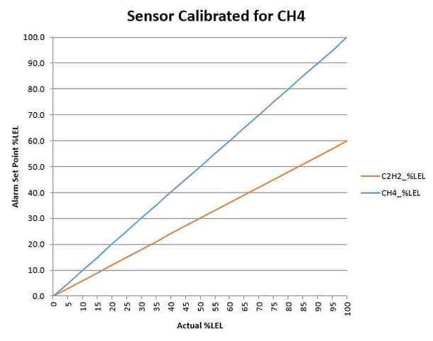
 But Martha, I need to measure LEL of both methane and acetylene! Ok, ok, ok. Ugh. If that incredibly smart scientist plots the data for both methane and acetylene on the same graph (the “plot” thickens, get it) when the sensor is calibrated for methane, AND also plots the data for both methane and acetylene on the same graph when the sensor is calibrated for acetylene, we start to SEE that we can use one of the calibrations of the sensor for both gases safely. Graphs below.
Don’t be overwhelmed with the graphs! Assume you want to evacuate your laboratory at 20% LEL. Go to 20% LEL on the Y-axis, then read across the graph until you intersect both plotted curves. At the intersection, read downward to the actual gas %LEL. You will notice that in this example, that if the sensor is calibrated for acetylene, then starting at 20% LEL on the Y-axis, both gases will be at or below 20% actual LEL. On the other graph, if the sensor is calibrated for methane and you start at 20% LEL on the Y-axis, you’ll find both gases are at OR ABOVE 20% actual LEL.
It would be prudent from a safety perspective to know that your flammable gases are at or below the display on your monitoring device. Conversely, it would be disconcerting to wonder how much more flammable gas you have above what is displayed on the monitoring device. Again, go back to the original question in the first paragraph, “…how one device can tell you percent of LEL for multiple gases knowing that each gas has a different 100% LEL?” If you are an informed engineer, and you know that one device can be calibrated safely to ensure you are below your chosen alarm level, the answer to the last question is, I PICKED THE PROPER GAS CALIBRATION TO ENSURE THE SAFETY OF MY LABORATORY.
The graphs shown in this blog are examples of what calibration curves might look like from your gas sensor manufacturer. After you examine these graphs, ask yourself, “what gas was used to calibrate my LEL sensor? AND, how does that compare to the flammable gas that I am trying to measure?” Wonder out loud to your gas sensor supplier and ask them for data that will make you feel comfortable using a chosen LEL sensor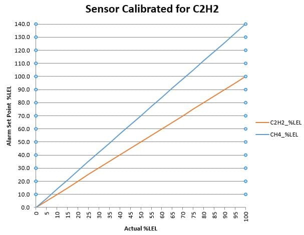
About the Author
John has a B.S. in Chemical Engineering from Penn State and a M.S. in Manufacturing Engineering from RPI. Prior to coming to Hallam-ICS, John had 30 years of experience working in Manufacturing/Process/Facilities Engineering for printed circuit board and semiconductor manufacturing. As a Senior Engineer at Hallam-ICS, John is responsible for the design and specification of Toxic Gas Monitoring Systems. He participates in all project design phases from concept through construction documents.
Read My Hallam Story
About Hallam-ICS
Hallam-ICS is an engineering and automation company that designs MEP systems for facilities and plants, engineers control and automation solutions, and ensures safety and regulatory compliance through arc flash studies, commissioning, and validation. Our offices are located in Massachusetts, Connecticut, New York, Vermont and North Carolina and our projects take us world-wide.
You May Also Like
These Related Stories

Metrology and Calibration - Weights and Measures
Basic Hazardous Gas Monitoring: Assessment and Selection of Ideal Gas Monitoring Technologies


No Comments Yet
Let us know what you think