
by Dylan Kerkes on Jul 16, 2026, 10:30:01 AM

Installing semiconductor equipment isn’t just about setting a tool in place and connecting a few hoses. It’s assembling a high-performance system where every detail matters.
From ultra-high-purity gases to cooling water and exhaust systems, successful semiconductor tool installation depends on tight coordination between engineering, installing contractors, tool vendors, users and facility managers.
From an overall facility perspective, the risks can vary in magnitude. Miss something early, and you’re not just fixing a drawing, you’re dealing with rework, schedule delays, and budget impacts.
From my 11 years of experience working on tool install projects; here are a few key lessons that can help you set your project up for success.
Try To Get Reliable Tool Data or Expect Rework
If there’s one thing that can cause problems, it’s beginning construction before receiving manuals and datasheets from the tool manufacture. Unfortunately, full utility requirements are usually not finalized until a purchase order has been signed and the final tool configuration has been established.
Depending on the process; semiconductor tools require a wide variety of utilities. Such as:
- Inert and hazardous gases
- Multi-stage filtered cooling water systems
- Corrosive exhaust and abatement
- Power and controls
Due to the complexity of the systems that serve these utilities, the tool details drive the entire design.
For example, if a new process gas is added late in the project because the tool configuration was not finalized before construction that can lead to pipe redesign, additional valves/regulators, safety systems, or even a new gas cabinet depending on the gas. The additional pipe material alone can cause a month or more delay due to the supply/demand for ultra-high purity stainless steel piping. These changes will also result in change orders from both the design and construction teams.
Think of it like building around a moving target. You can do it, but you might miss and build the wrong thing. Missing will cost you time and money.
Starting with incomplete utility information is where many projects start to lose efficiency. The design is based on assumptions and later updates ripple across multiple systems.
Lesson:
Push to get final equipment details before moving too far into design. That doesn’t always happen, however, so be meticulous in documenting requirements and changes. Articulate the impacts of a change to the team when it’s introduced.
Lock in the Layout Early (It’s Hard to Move a System Later)
Once you have equipment data, the next critical step is layout.
Unfortunately equipment layout is rarely straightforward. In semiconductor environments your balancing:
- Main tool footprint
- Support equipment
- Vacuum pumps
- Chillers
- Gas cabinets
- Electronic cabinets
- Equipment clearances
- Maintenance access including removable panels or doors
- Utility routing such as exhaust ducts, vacuum forelines, gas piping, cooling water and drains.
- Existing conditions (especially in retrofit spaces)
- Wall bulkhead details
- Multi-level installations such as a building that has a subfab
.png?width=637&height=498&name=Figure%201%20compact%20subfab(2).png)
Figure 1:Compact Subfab
Once detailed design begins, especially in 3D, moving things becomes time consuming and expensive quickly.
It’s like painting a landscape with trees and a mountain. You’re applying the final brush strokes to detail the foliage, and your client walks into the studio and asks you to move the mountain and rework all the trees.
Even a small layout shift can force cascading updates affecting all trades leading to a renewed coordination update.
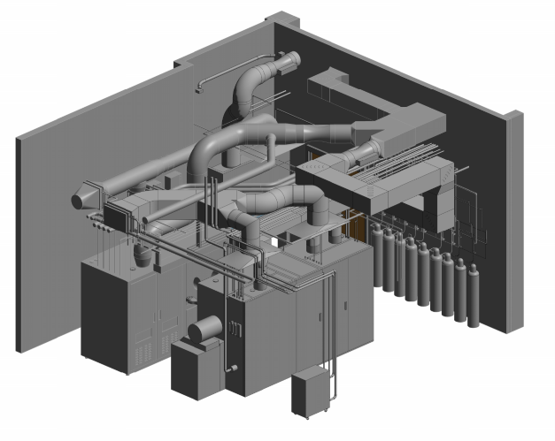
Figure 2: Even in Revit it’s hard to move all that piping and ductwork after its modeled!
Lesson:
Late layout changes aren’t isolated; they typically affect multiple disciplines at once.
Lock in your equipment layout early before detailed engineering begins.
Utility Design: Where Things Get More Complex
The equipment itself is only one piece of the puzzle. Everything connected to it is what makes the system work.
Concurrently with layout planning you should also think about required utilities. If it’s an existing building do the facilities have enough capacity to handle additional loads? What support equipment is required such as gas cabinets or point of use chillers? How much clearance do you need to make utility connections? Where are the disconnects going?
Once the layout is established the focus can shift to detailed utility routing. Below are a few common utilities you may encounter:
Gas Systems
These tools often require a variety of gases depending on the process and recipe that will be used. Most equipment will require N2 for purging or as a process gas and compressed dry air for pneumatic valve actuation in the equipment. Some additional example gases below;
- O2 (oxidizer)
- SF6
- He
- Ar
- 5% H2/N2
- H2 (flammable)
- Chlorine (toxic, corrosive)
- Silane (pyrphoric)
- BCl3 (toxic)
- Ammonia (toxic)
Gas distribution often requires:
- Pressure regulation
- Shutoff valves
- Filters
- Exhausted enclosures (gas cabinets or valve manifold boxes)
- Specialized piping (ultra-high purity or coax)
- Gas Monitoring and shutdown integration
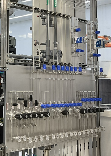
Figure 3: Tool non-hazardous gas regulation panel
Toxic gases require coaxial or contained piping. Coaxial piping has a carrier pipe where the gas flows and then an outer pipe that serves as protection in case the inner pipe leaks. For a deeper look at best practices, see our blog on containment piping for specialty gases and key design considerations
Gas distribution is one of the main reasons to finalize tool configuration/details due to the required support equipment and expensive piping. In a compact layout it may be tough to fit another gas cylinder or cabinet.
Lesson:
Pay close attention to the gas requirements and manuals to avoid missing a connection. Confirm assumptions directly with the tool vendor.
Cooling Water Systems: It’s Not Just About Flow
The next major utility for semiconductor tools is cooling water. Requirements can vary from tool to tool; general considerations listed below:
- Temperature stability
- Differential pressure
- Flow rate
- Supply pressure
- Filtration
- Water quality (including resistivity)
It’s important to note that at higher resistivity levels the water becomes surprisingly aggressive. Water higher than 10,000-ohm resistivity will pull ions from incompatible piping materials if the system isn’t designed correctly. This is another area where paying close attention to the tool manual is imperative. The resistivity requirement is often listed there.
Also make note of the differential pressure. Tools often require much higher pressures compared to your fan coil.
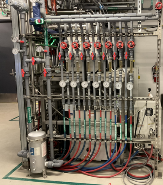
Figure 4: Cooling water manifold on a 1-mega ohm system
If temperature stability is critical, local water to water heat exchangers can be used to:
- Maintain tight temperature tolerances
- Meet tool-specific water quality requirements
- Isolate the tool from facility fluctuations
Lesson:
Don’t just design the cooling water system for flow; pay attention to the quality and other parameters listed in the data sheets. Compare these parameters to your facility system and verify your good to run.
Exhaust Systems
Another critical utility system is exhaust. The two major types of exhaust are corrosive and solvent. The exhaust type and system construction depends on the materials used in the tool.
This is one area I have found where blindly following the tool manuals can get you into trouble.
Tool exhaust connection sizes are often not large enough for real operating conditions. Designing based on those alone can lead to underperforming systems.
Key considerations include:
- Proper duct sizing based on actual flow
- Dedicated exhaust for specific chemicals
- Integration with gas monitoring systems
- Flexibility for maintenance work
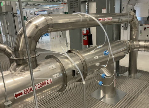
Figure 5: Exhaust duct with gas monitoring
Many facilities also include flexible spot exhaust ducts (snorkels) for technicians working on the equipment. Ambient detection supplies continuous monitoring systems for safety in addition to exhaust detection.
Lesson:
Design exhaust systems based on performance, not just what’s shown on the cut sheet.
For a deeper dive into how ventilation impacts safety and performance in these environments, check out our overview of ventilation of gas cabinets and exhausted enclosures.
The Benefits of Prefabrication
Given the complexity of these systems, prefabrication during the design phase can offer real advantages. Common components that can be prefabricated include gas cabinets, point of use utility manifolds, vacuum pump/chiller/cryo compressor support racks, and complex ductwork to name a few.
Prefabrication benefits include:
- Quality control
- Consistency
- Reduced field labor
- Reduction in schedule (components can be built in parallel with the design)
The tradeoff is that it requires earlier coordination, you need to know what you’re building before you place the order. If a requirement changes after a PO is released for a prefabricated item it can result in expensive re-work and delay.
Projects that benefit most from prefabrication are the ones where design decisions are made early and remain stable.
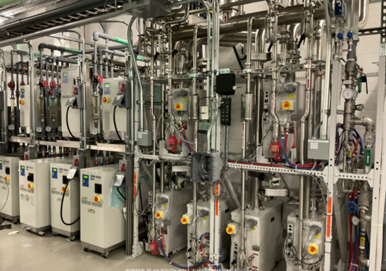
Figure 6:Pre fabricated chiller and pump racks
Lesson:
You can use prefabrication for repeatable systems and time saving but make sure the design is far enough along to support it.
Coordinate Early and Coordinate Often
There's a saying in martial arts: “Tap early and tap often.” Tapping (patting your partner’s arm or slapping the ground) is a safety measure in martial arts to signify that a submission (ex. armbar or choke) is working. Once you know that your partner’s choke is working you tap the person so they stop choking you and you both can continue training. Without the tap; if the submission is applied any further it will result in joint damage or passing out. Coordination is a similar thing – if you don’t coordinate early and talk to your team often it can result in a painful project!
Successful projects depend on alignment between:
- Tool vendors
- Mechanical Engineers
- Electrical Engineers
- Architects
- Structural engineers
- Contractors
- Facility teams
Some example issues of poor coordination are:
- Conflicting layouts
- Incorrect utility connections
- Missing utility connections
- Utility clashing (ex. a pipe in the way of a disconnect clearance)
- Late-stage design or in field changes.
Any of these issues can lead to costly re-work.
Lesson:
Early engagement and consistent communication are the most effective ways to reduce project risk.
Coordination challenges don’t stop at mechanical systems. Controls integration is another area where early involvement can prevent major downstream issues during startup and commissioning. For more on this, read why owners and EPCs should engage a controls integrator early in the engineering phase.
FAQ: Semiconductor Tool Installation
Why is it important to wait for final equipment specifications?
Because even small changes in tool requirements, like adding gas or changing flow rates, can require major redesign of utilities, leading to cost and schedule impacts.
What utilities do semiconductor tools typically require?
Most tools require specialty gases, cooling water, exhaust systems, vacuum systems, and electrical infrastructure, all of which must be carefully coordinated.
Why can’t you rely on the tool manufacturer’s connection sizes?
Because they’re often undersized for real-world conditions. Systems should be designed based on actual flow and pressure requirements.
How can teams reduce risk during installation?
By locking in equipment specs early, finalizing layouts before detailed design, and working with teams experienced in semiconductor facility systems.
Conclusion
Semiconductor tool installation isn’t just about opening the box and setting it into place. It’s about a well-engineered design, coordination, timing, and getting the details right early.
When projects are designed and executed well everything flows; design, construction, and long-term operation work synergistically to give you the best final product.
Planning a Tool Installation or Facility Upgrade?
Whether you’re adding a single tool or upgrading an entire facility, having the right engineering team can make all the difference in cost, schedule, build quality and long-term performance.
Hallam-ICS specializes in semiconductor facility design. We can assist you with equipment layout, utility infrastructure, clean room HVAC design, specialty gas piping, power, UPS, process controls and gas monitoring design/installation. We work in Revit 3d design software with detailed equipment models to enhance coordination between trades. With our decades of experience in this field, we know construction. Unlike other design firms we will continue to guide and support the project well after the design concludes. We work closely with facility managers and project teams to help align design decisions early and avoid costly issues later in the project.
If you’re planning new equipment installation in an existing space, evaluating an upgrade, or building a whole new facility please don’t hesitate to contact us on how we can help you with your next project.
About the author
Dylan is a driven Mechanical Engineer with experience in both design and project management. He is a graduate of Rensselaer Polytechnic Institute with B.S. in Mechanical Engineering and a registered professional engineer (PE) in several states. He has been with Hallam-ICS over 11 years in which most of his time has been spent designing facility’s for semiconductor equipment. He has led the tool install design at MIT.nano for the last 6 years. Dylan also holds a 5th degree black belt in Kenpo Jujitsu and a brown belt in Brazilian Jujitsu
Read My Hallam Story
About Hallam-ICS
Hallam-ICS is an engineering and automation company that designs MEP systems for facilities and plants, engineers control and automation solutions, and ensures safety and regulatory compliance through arc flash studies, commissioning, and validation. Our offices are located in Massachusetts, Connecticut, New York, Vermont, North Carolina and Texas and our projects take us world-wide.
Why Toxic Gas Monitoring Is Critical for Labs and Manufacturing Facilities

The Benefits of Turnkey Engineering Solutions: One Partner from Design to Commissioning
No Comments Yet
Let us know what you think