
by Bill Neuburger and Ash Kreider on Jul 15, 2021 10:30:00 AM
In a previous blog series, DC to AC Drive Conversions, we discussed ways to ensure your change from Direct Current (DC) motors to Alternating Current (AC) motors is successful. Here we offer an example of an evaluation we performed at a Northeast US paper mill. We studied replacing an existing pre-dry stack 25 horsepower DC motor with a new 30 horsepower AC motor, motor controller (variable frequency drive), and controls (onboard the controller). The owner chose a 30 hp motor as they have this elsewhere in the mill and keep one on the shelf as a spare.
We evaluated first the proposed motor’s suitability for service (power, torque, and speed) and second to understand needed changes to the existing motor, gearbox, and bearing support structure.
The client collected motor power data during production in February 2020, using a temporary meter on the existing DC motor controller’s line. Using the power data, line speed, motor speed, and the drive roll’s circumference we calculated the motor’s delivered torque. We created these graphs from the owner’s data and from our calculations. Figure 1 is simply the motors electrical power demand over the time period of interest. Figure 2 identifies the demand torque and power at different operating speeds.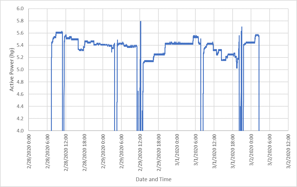
Figure 1: AC Electrical Power vs Time
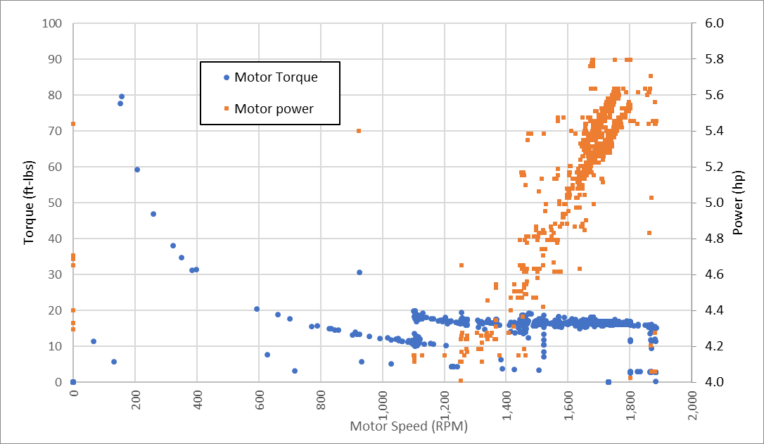
Figure 2: Motor Power and Torque vs Motor Speed
We made these observations of power and torque.
- The maximum power required by the process for the provided time period was 4,300 W, or 5.77 horsepower. This occurred at a motor speed of about 1800 RPM. We conservatively assume that the DC drive efficiency is 99%, so the motor was consuming a maximum of 5.71 horsepower.
- Torque- The process required a relatively constant motor torque of 16-18 foot-pounds across motor speed of 1400-1800 RPM. The startup torque (was about 80 foot-pounds).
 We added the proposed motor’s torque and power information at different motor speeds to the chart in Figure 2. We observed that the proposed motor has adequate power and torque at all motor speeds. See Figure 3.
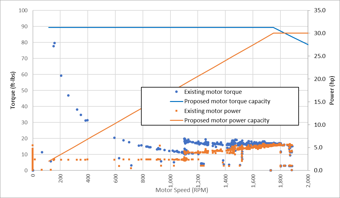
Figure 3: Existing motor loads compared to proposed motor capacity
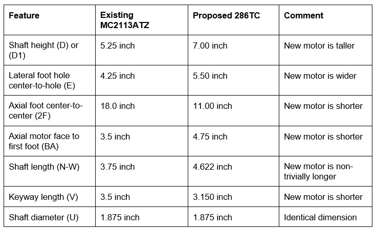
Knowing the motor would mechanically and electrical perform adequately, we moved on to evaluating the geometric differences between the existing DC motor and the proposed AC motor (with a 286TC frame). The existing motor is a Baldor MC2113ATZ unit which did not follow the standard NEMA frame numbering nomenclature. However, we were able to locate an old Baldor datasheet which gave us the geometry for a MC2113ATZ frame. See table 1 below for a comparison of the key geometric features.
We proposed options for modifications to the existing built up steel and concrete base, considering field cutting and welding. After considerations of various choices, we designed a new steel base to match the existing gearbox, existing bearings, and new motor. The owner will have it fabricated at a local steel shop and install it during an outage at their convenience.
This exercise combined several pieces of information that are needed to choose an acceptable AC replacement motor.
- Power measurements. One can make calculation-only comparisons, but we prefer measured data.
- Catalog data for the existing and new motors
- Field observations and measurements
If you are considering replacing an existing DC motor, you will likely need to gather similar information. We can answer questions you might have regarding this process and would be happy to speak with you.
About the authors
Bill has been a mechanical engineer since 1995 and with Hallam-ICS since 2010. His career has brought him to the top of the Transamerica Pyramid Center, chemical plants, underground mines, paper mills, and semiconductor fabrication facilities. He has experience designing, specifying and installing mechanical and electrical systems in the built environment covering industrial, institutional and commercial facilities.
Read My Hallam Story
Ash Kreider is a Mechanical Engineer at Hallam-ICS. He has process engineering experience in multiple industries. He currently designs systems for a wide range of applications including gas distribution, cryogenic fluid recovery, process equipment hookup and HVAC.
Read My Hallam Story
About Hallam-ICS
Hallam-ICS is an engineering and automation company that designs MEP systems for facilities and plants, engineers control and automation solutions, and ensures safety and regulatory compliance through arc flash studies, commissioning, and validation. Our offices are located in Massachusetts, Connecticut, New York, Vermont and North Carolina and our projects take us world-wide.

Main Instrument Vendor (MIV) Process Execution - Design

How Emerson Flow Meters and Ignition Dashboards Drive Efficiency
No Comments Yet
Let us know what you think